44D30-02-2-AJN Grayhill Inc, 44D30-02-2-AJN Datasheet - Page 10
44D30-02-2-AJN
Manufacturer Part Number
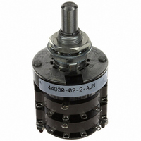
44D30-02-2-AJN
Description
SW ROTARY MIL DP 2DECK ADJ 6POS
Manufacturer
Grayhill Inc
Series
44r
Type
Rotaryr
Specifications of 44D30-02-2-AJN
Angle Of Throw
30°
Number Of Positions
2 ~ 6
Number Of Decks
2
Number Of Poles Per Deck
2
Circuit Per Deck
DP6T
Contact Rating @ Voltage
1A @ 115VAC
Actuator Type
Flatted (6.35mm dia)
Mounting Type
Panel Mount
Termination Style
Solder Lug
Orientation
Vertical
No. Of Poles
2
No. Of Switch Positions
6
Contact Current Ac Max
1A
Contact Current Dc Max
1A
Contact Voltage Ac Max
115V
Contact Voltage Dc Max
115V
Circuitry
DP6T
Brand/series
44 Series
Current, Rating
1 A
Dielectric Strength
1000 VAC
Material, Contact
Silver Alloy
Mechanical Life
100,000 Cycles
Number Of Poles
2
Termination
Solder
Voltage, Rating
115 V
Features Choice Include
shaft⁄panel seal, adjustable stops
Lead Free Status / RoHS Status
Lead free / RoHS Compliant
Lead Free Status / RoHS Status
Lead free / RoHS Compliant, Lead free / RoHS Compliant
Other names
44D30-02-2-AJN
GH7346
Q1410080
GH7346
Q1410080
Available stocks
Company
Part Number
Manufacturer
Quantity
Price
Company:

Part Number:
44D30-02-2-AJN
Manufacturer:
GHY
Quantity:
10


ACCESSORIES
ORDERING INFORMATION: Single Shaft Switches, Add-A-Pot Switches
ORDERING INFORMATION: Concentric Shaft Rotary Switches
Available from your local Grayhill Distributor
Grayhill, Inc. • 561 Hillgrove Avenue • LaGrange, Illinois
Internal Tooth Lockwasher–Figure A
For a
outside diameter, .022" (0,56) thickness. Material
is cadmium-plated steel. Part No. 12Q1272-1
For a
0.400" (10,16) outside diameter, .018"
(0,46) thickness. Material is steel, tin/
zinc plated.
Non-Turn Washer–Figure B
Can be ordered as extra hardware for the
Series 5000, 24, 42, 43, 44, 54, 71B, 53, 57 and
59 rotary switches. The internal key of the
washer slides into the bushing keyway. The
right angle tab locks into a predrilled hole on
the back side of the mounting panel. Material is
brass, tin/zinc plated. Part No. 12C1087-1
Panel Seal Kit–Figure C
Sold as a separate item to seal the switch
44M30–02–1–12N–F
* All rotary switches that are required to have military designated markings and testing adhering to MIL-3786 are to be ordered by specifying
the military part number identified on the appropriate slash sheet.
43M02110N–M03203S
* All rotary switches that are required to have military designated markings and testing adhering to MIL-3786 are to be ordered by specifying
the military part number identified on the appropriate slash sheet.
3
/
8
1
" bushing. Approximately 0.500" (12,7)
/
4
" bushing. Approximately
Series: Determined by the type of switch and
the angle of throw
Style*: Letter(s) from the Choices and Limitations chart
Angle of Throw: Must agree with Series Number
Number of Decks: As limited by the angle of throw, the poles per deck, switch style and type of contacts
Stop Arrangement: Add letter F to a one pole per deck switch with the maximum number of positions for
a stop between position 1 and the last position. Leave blank for continuous rotation
Type of Contacts: N = Non-shorting; S = Shorting
Positions Per Pole: Requires 02 positions as a minimum to maximum allowable dependent on the angle
of throw and poles per deck. Use AJ for adjustable stops (Styles D and UD).
Poles Per Deck: As limited by angle of throw, switch series and style
Series: Determined by the angle of throw, applicable to both sections
Style*: Letter(s) from the Choices and Limitations chart
Number of Decks: As limited by the number of poles per deck
Poles Per Deck: As limited by the angle of throw
Positions Per Pole: Requires 02 positions as a minimum to the maximum allowable dependent on the angle
of throw and the poles per deck
Type of Contacts: N=Non-shorting, S=Shorting. All one pole per deck switches with the maximum number
of positions are continuous rotation
The limitations listed for Section A apply to Section B
Type of Contacts
Positions Per Pole
Poles Per Deck
Number of Decks
Style
FIGURE A
bushing to the panel. The kit consists of four
items: a grooved hex nut, a keyed washer, a
keyed seal and a non-turn washer. Assembly is
described on Page J-53. Dimensions of panel
seal kit items are shown in Figure C. This kit
seals the bushing to the panel; it does not seal
the shaft to the bushing. Not usable with
adjustable stop switches. Part No. 42-24
(15,88 ± 0,25) DIA.
For prices and discounts, contact a local Sales Office, an authorized local Distributor or Grayhill.
.375 + .004 – .000
(9,53 + 0,10) DIA.
C L
(9,53 ± 0,13)
.375 ± .005
60525-5997 • USA • Phone: 708-354-1040 • Fax: 708-354-2820 • www.grayhill.com
.625 ± .010
.125 ± .003
(3,18 ± 0,08)
Section A (front)
Section B (rear)
Non-Turn Washer
Multi-Deck Rotary Switches
.032
± .002
(0,81
± 0,05)
.187 ± .010
(4,75 ± 0,25)
.045 ± .003
(1,14 ± 0,08)
Seal
FIGURE C
.060 ± .002
(1,52 ± 0,05)
.154
+ .004
–.000
(3,91
+ 0,10
–0,00)
DIA.
Keyed Washer
.010 ± .002
(0,25 ± 0,05)
(11,10 ± 0,25)
.120 ± .003
(3,18 ± 0,08)
.437 ± .010
.625 ± .010
(15,88 ± 0,25)
DIA.
.376 + .003 –.000
(9,55 + 0,08 –0,00)
DIA.
FIGURE B
Hex Nut
.088 (2,24)/
.093 (2,36)
.562 (14,27)
ACROSS
FLATS
.032 ± .002
(0,81 ± 0,05)
.125 ± .010
(3,18 ± 0,25)
Rotary
31
Related parts for 44D30-02-2-AJN
Image
Part Number
Description
Manufacturer
Datasheet
Request
R

Part Number:
Description:
SW ROTARY MIL SP 2DECK ADJ 12POS
Manufacturer:
Grayhill Inc
Datasheet:

Part Number:
Description:
Rotary Switch, Standard, Adjustable Stops, 30°
Manufacturer:
Grayhill Inc
Datasheet:
Part Number:
Description:
Rotary Switch, Standard, Adjustable Stops, 30°
Manufacturer:
Grayhill Inc
Part Number:
Description:
Rotary Switch, Standard, Adjustable Stops, 30°
Manufacturer:
Grayhill Inc
Datasheet:
Part Number:
Description:
Rotary Switch, Standard, Adjustable Stops, 30°
Manufacturer:
Grayhill Inc

Part Number:
Description:
Rotary Switch, Standard, Adjustable Stops, 30°
Manufacturer:
Grayhill Inc
Datasheet:
Part Number:
Description:
Rotary Switch, Standard, Adjustable Stops, 30°
Manufacturer:
Grayhill Inc
Part Number:
Description:
44D30-01-4-AJS Table Stops, 30°
Manufacturer:
Grayhill Inc
Datasheet:
Part Number:
Description:
44D30-07-1-AJS Table Stops, 30°
Manufacturer:
Grayhill Inc
Datasheet:
Part Number:
Description:
44D30-10-1-AJS Table Stops, 30°
Manufacturer:
Grayhill Inc
Datasheet:
Part Number:
Description:
44D30-11-2-AJN Table Stops, 30°
Manufacturer:
Grayhill Inc
Datasheet:
Part Number:
Description:
Rotary Switch, Standard, Adjustable Stops, 30°
Manufacturer:
Grayhill Inc
Datasheet:
Part Number:
Description:
Rotary Switch, Standard, Adjustable Stops, 30°
Manufacturer:
Grayhill Inc