MS5541-CM Measurement Specialties Inc., MS5541-CM Datasheet - Page 13
MS5541-CM
Manufacturer Part Number
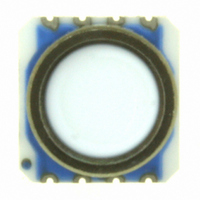
MS5541-CM
Description
MODULE 14 BAR PRESSURE MINI SNSR
Manufacturer
Measurement Specialties Inc.
Datasheet
1.MS5541-CM.pdf
(19 pages)
Specifications of MS5541-CM
Pressure Type
Absolute
Operating Pressure
203.05 PSI, 14bar
Output
Digital
Voltage - Supply
2.2 V ~ 3.6 V
Termination Style
PCB
Operating Temperature
-40°C ~ 85°C
Package / Case
6.2 x 6.4mm Module
Lead Free Status / RoHS Status
Lead free / RoHS Compliant
Other names
223-1099-2


SERIAL INTERFACE
The MS5541C communicates with microprocessors and other digital systems via a 3-wire synchronous serial
interface as shown in Fig. 1. The SCLK (Serial Clock) signal initiates the communication and synchronizes the
data transfer with each Bit being sampled by the MS5541C on the rising edge of SCLK and each Bit being sent
by the MS5541C on the rising edge of SCLK. The data should thus be sampled by the microcontroller on the
falling edge of SCLK and sent to the MS5541C with the falling edge of SCLK. The SCLK-signal is generated by
the microprocessor’s system. The digital data provided by the MS5541C on the DOUT pin is either the
conversion result or the software calibration data. In addition the signal DOUT (Data Out) is also used to indicate
the conversion status (conversion-ready signal, see below). The selection of the output data is done by sending
the corresponding instruction on the pin DIN (Data Input).
Following is a list of possible output data instructions:
Every communication starts with an instruction sequence at pin DIN. Fig. 6 shows the timing diagrams for the
MS5541C. The device does not need a ‘Chip select’ signal. Instead there is a Start Sequence (3-Bit high) before
each Setup Sequence and Stop Sequence (3-Bit low) after each Setup Sequence. The Setup Sequence consists
in 4-Bit that select a reading of pressure, temperature or calibration data. In case of pressure- (D1) or
temperature- (D2) reading the module acknowledges the start of a conversion by a low to high transition at pin
DOUT during the last bit of the Stop Sequence.
Two additional clocks at SCLK are required after the acknowledge signal. Then SCLK is to be held low by the
microcontroller until a high to low transition on DOUT indicates the end of the conversion.
This signal can be used to create an interrupt in the microcontroller. The microcontroller may now read out the
16-Bit word by giving another 17 clocks on the SLCK pin. It is possible to interrupt the data read-out sequence
with a hold of the SCLK signal.
It is important to always read out the last conversion result before starting a new conversion.
The RESET-sequence is special as its unique pattern is recognized by the module in any state. By consequence
it can be used to restart if synchronization between the microcontroller and the MS5541C has been lost. This
sequence is 21-Bit long. The DOUT signal might change during that sequence (see Fig. 6e). It is recommended
to send the RESET sequence before first CONVERSION sequence to avoid hanging up the protocol permanently
in case of electrical interference.
DA5541C_001.doc
000055411194 ECN1037
Bit0
Conversion start for pressure measurement and ADC-data-out "D1":
Start-bit
Bit1
Bit2
sequence: START+P-measurement
• Conversion start for pressure measurement and ADC-data-out
• Conversion start for temperature measurement and ADC-data-out
• Calibration data read-out sequence for word 1
• Calibration data read-out sequence for word 2
• Calibration data read-out sequence for word 3
• Calibration data read-out sequence for word 4
• RESET sequence
Bit3
Bit4
Setup-bits
Bit5
start of conversion
Bit6
Bit7
Stop-bit
Bit8 Bit9
end of conversion
Fig. 6a: D1 acquisition sequence
conversion
February 19th, 2008
(33ms)
DB7
DB6 DB5 DB4 DB3 DB2 DB1
ADC-data out MSB
DB0 DB7 DB6 DB5 DB4 DB3 DB2 DB1 DB0
“D1”
“D2”
ADC-data out LSB
(Figure 6a)
(Figure 6b)
(Figure 6c)
(Figure 6d)
(Figure 6c)
(Figure 6d)
(Figure 6e)
13
Related parts for MS5541-CM
Image
Part Number
Description
Manufacturer
Datasheet
Request
R


Part Number:
Description:
MODULE BAROMETER MINITURE SENSOR
Manufacturer:
Measurement Specialties Inc.
Datasheet:

Part Number:
Description:
SENSOR PRESSURE 15PSIG SMD
Manufacturer:
Measurement Specialties Inc.
Datasheet:

Part Number:
Description:
SENSOR PRESSURE 100PSIG SMD
Manufacturer:
Measurement Specialties Inc.
Datasheet:

Part Number:
Description:
SENSOR PRESSURE 100PSIA SMD
Manufacturer:
Measurement Specialties Inc.
Datasheet:

Part Number:
Description:
SENSOR PRESSURE 100PSIA SMD
Manufacturer:
Measurement Specialties Inc.
Datasheet:

Part Number:
Description:
SENSOR PRESSURE 50PSIA SMD
Manufacturer:
Measurement Specialties Inc.
Datasheet: