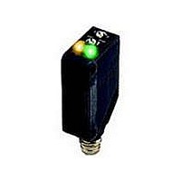
E3Z-T67 Omron, E3Z-T67 Datasheet - Page 16

E3Z-T67
Manufacturer Part Number
E3Z-T67
Description
30M T/B NPN 4 PIN M8 CONN
Manufacturer
Omron
Series
E3Zr
Datasheet
1.E3Z-T61-L.pdf
(19 pages)
Specifications of E3Z-T67
Sensing Distance
1181.102" (30m)
Sensing Method
Through-Beam
Output Configuration
NPN - Dark-ON/Light-ON - Selectable
Mounting Type
Bracket Mount
Current - Supply
35mA
Voltage - Supply
12 V ~ 24 V
Response Time
1ms
Package / Case
Module, Connector
Lead Free Status / RoHS Status
Lead free / RoHS Compliant
Lead Free Status / RoHS Status
Lead free / RoHS Compliant, Lead free / RoHS Compliant
Other names
E3ZT67
Dimensions
Sensors
* Models numbers for Through-beam Sensors (E3Z-T@@) are for sets that include both the Emitter and Receiver.
Through-beam*
Pre-wired Models
E3Z-T61(K)
E3Z-T81(K)
E3Z-T61A
E3Z-T81A
E3Z-T62(-G0)
E3Z-T82(-G0)
Through-beam*
Connector Models
E3Z-T66
E3Z-T86
E3Z-T66A
E3Z-T86A
E3Z-T67(-G0)
E3Z-T87(-G0)
The model number of the Emitter is expressed by adding "-L" to the set model number (example: E3Z-T61-L 2M), the model number of the Receiver, by adding "-D"
(example: E3Z-T61-D 2M.) Refer to Ordering Information to confirm model numbers for Emitter and Receivers.
10.4
2.1
31
31
2.1
31
31
2.1
31
31
10.4
2.1
31
31
4 dia. vinyl-insulated round cable with 3 conductors
(Conductor cross section: 0.2 mm
Insulator diameter:1.1 mm), Standard length: 2 m
11
11
4 dia. vinyl-insulated round cable with 2 conductors
(Conductor cross section: 0.2 mm
Insulator diameter: 1.1 mm), Standard length: 2 m
11
11
Emitter
Receiver
Emitter
Receiver
10.8
10.8
10.8
10.8
10.8
10.8
7.2
7.2
7.2
10.8
10.8
Operation Indicator (orange)
Operation Indicator (orange)
7.2
Lens
Lens
Lens
Lens
Stability indicator (green)
Stability indicator (green)
Power indicator (orange)
M8 connector
M8 connector
Power indicator
(orange)
25.4
25.4
Two, M3
25.4
Two, M3
25.4
Two, M3
2.8
Two, M3
2.8
2.8
2
2.8
2
(AWG24),
(AWG24),
3
3
3
3
7.5
9.75
7.5
11.2
9.75
12
12
11.2
20
20
20
20
20
20
20
20
Tolerance class IT16 applies to dimensions in this data sheet unless otherwise specified.
4.5
4.5
Operation selector
Sensitivity adjuster
12.7
12.7
Operation
selector
Sensitivity
adjuster
12.7
12.7
Pin 2 is not used.
Pin 4 is not used.
Pins 2 and 4 are not used.
Terminal
Pins 2 and 4 are not used.
Pin 4 is not used.
Pin 2 is not used.
Terminal
Terminal
Terminal
Terminal
Terminal
(Excluding -G0)
No.
No.
No.
1
2
3
4
(Excluding -G0)
No.
No.
No.
1
2
3
4
1
2
3
4
1
2
3
4
1
2
3
4
1
2
3
4
(-G0)
(-G0)
Specifi-
cations
Specifi-
Specifi-
cations
Output
cations
Specifi-
Specifi-
Specifi-
cations
cations
cations
Output
+V
0V
Input
---
Input
+V
0V
+V
0V
+V
+V
---
0V
+V
0V
0V
---
---
---
---
---
---
* The Emitter cable has two conductors and the
Receiver cable has three conductors.
M8 Pre-wired Connector
(E3Z-T@@K-M3J)
M12 Pre-wired Connector
(E3Z-T@@-M1J)
Press-fit e-CON Pre-wired Connector
Clamp-type e-CON Pre-wired Connector
(E3Z-T61-ECON-C)
4 dia. vinyl-insulated round cable with
2 or 3 conductors,
Standard length: 0.3 m
4 dia. vinyl-insulated round cable with
2 or 3 conductors,
Standard length: 2m
4 dia. vinyl-insulated round cable with
2 or 3 conductors,
Standard length: 0.3 m,0.5m, and 2m
4 dia. vinyl-insulated round cable with
2 or 3 conductors,
Standard length: 0.3 m
15.6
18
M12×1
1
2
3
4
1
2
3
4
M8
5.9
6
15.8
15
(Unit: mm)
1
2
2
1
E3Z
4
4
3
3
16


