VSKT500-16 Vishay, VSKT500-16 Datasheet - Page 6
VSKT500-16
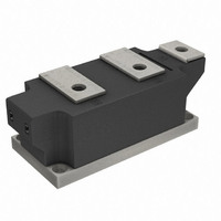
Manufacturer Part Number
VSKT500-16
Description
SCR DBL 2SCR 1600V 500A MAGNAPAK
Manufacturer
Vishay
Datasheet
1.VSKH500-12.pdf
(8 pages)
Specifications of VSKT500-16
Structure
Series Connection - All SCRs
Number Of Scrs, Diodes
2 SCRs
Voltage - Off State
1600V
Current - Gate Trigger (igt) (max)
200mA
Current - On State (it (av)) (max)
500A
Current - On State (it (rms)) (max)
785A
Current - Non Rep. Surge 50, 60hz (itsm)
17800A, 18700A
Current - Hold (ih) (max)
500mA
Mounting Type
Chassis Mount
Package / Case
SUPER MAGN-A-PAK
Rated Repetitive Off-state Voltage Vdrm
1600 V
Off-state Leakage Current @ Vdrm Idrm
100 mA
Holding Current (ih Max)
500 mA
Mounting Style
Screw
Breakover Current Ibo Max
18700 A
Gate Trigger Current (igt)
200 mA
Gate Trigger Voltage (vgt)
3 V
Repetitive Peak Forward Blocking Voltage
1600 V
Lead Free Status / RoHS Status
Contains lead / RoHS non-compliant
Other names
*IRKT500-16
IRKT500-16
IRKT500-16
IRKT500-16
IRKT500-16


VSKT500-..PbF, VSKH500-..PbF, VSKL500-..PbF
Vishay Semiconductors
ORDERING INFORMATION TABLE
Note
• To order the optional hardware go to
www.vishay.com
6
10000
Fig. 10 - On-State Voltage Drop Characteristics
1000
100
0.5
Instantaneous On-s tate Voltage (V)
1
1.5
Device code
T = 25°C
T = 130°C
2
DiodesAmericas@vishay.com, DiodesAsia@vishay.com,
J
J
100
For technical questions within your region, please contact one of the following:
0.1
2.5
10
0.001
1
VSK.500.. S eries
Per Junction
b) Recommended load line for
a) R ecommended load line for
R ectangular gate pulse
3
tr<=1 µs
<=30% rated di/ dt : 10V, 10ohms
rated di/ dt : 20V, 10ohms; tr<=1 µs
www.vishay.com/doc?95172
3.5
(SUPER MAGN-A-PAK Power Modules), 500 A
VGD
2
3
4
5
1
VSK
4
Thyristor/Diode and Thyristor/Thyristor
1
0.01
IGD
4.5
-
-
-
-
-
Fig. 12 - Gate Characteristics
T
2
Circuit configuration (see end of datasheet)
Current rating
Voltage code x 100 = V
Module type
Lead (Pb)-free
Instantaneous Gate Current (A)
0.1
500
3
VSK.500.. S eries
(b)
-
(a)
1
Frequency Limited by PG(AV)
16
4
Fig. 11 - Thermal Impedance Z
(1) PGM = 10W, tp = 4ms
(2) PGM = 20W, tp = 2ms
(3) PGM = 40W, tp = 1ms
(4) PGM = 60W, tp = 0.66ms
RRM
0.001
DiodesEurope@vishay.com
0.01
0.1
0.001
(see Voltage Ratings table)
PbF
5
VSK.500.. S eries
Per Junc tion
10
S quare Wave Pulse Duration (s)
(1)
0.01
(2)
(3)
0.1
(4)
S teady S tate Value:
R
(DC Operation)
100
thJC
1
= 0.065 K/ W
thJC
Document Number: 94420
10
Characteristics
Revision: 02-Jul-10
100
Related parts for VSKT500-16
Image
Part Number
Description
Manufacturer
Datasheet
Request
R

Part Number:
Description:
SCR DBL 2SCR 1200V 500A MAGNAPAK
Manufacturer:
Vishay
Datasheet:
Part Number:
Description:
SCR DBL 2SCR 800V 500A MAGNAPAK
Manufacturer:
Vishay
Datasheet:
Part Number:
Description:
SCR DBL 2SCR 1400V 500A MAGNAPAK
Manufacturer:
Vishay
Datasheet:

Part Number:
Description:
SCR Modules 500 Amp 1200 Volt 785 Amp IT(RMS)
Manufacturer:
Vishay
Part Number:
Description:
SCR Modules 500 Amp 1400 Volt 785 Amp IT(RMS)
Manufacturer:
Vishay
Part Number:
Description:
SCR Modules 500 Amp 800 Volt 785 Amp IT(RMS)
Manufacturer:
Vishay
Part Number:
Description:
SCR Modules 500 Amp 1600 Volt 785 Amp IT(RMS)
Manufacturer:
Vishay

Part Number:
Description:
Thyristor/Diode and Thyristor/Thyristor
Manufacturer:
Vishay Siliconix
Datasheet:
Part Number:
Description:
357-036-542-201 CARDEDGE 36POS DL .156 BLK LOPRO
Manufacturer:
Vishay
Datasheet:
Part Number:
Description:
357-036-542-201 CARDEDGE 36POS DL .156 BLK LOPRO
Manufacturer:
Vishay
Datasheet:
Part Number:
Description:
357-036-542-201 CARDEDGE 36POS DL .156 BLK LOPRO
Manufacturer:
Vishay
Datasheet:
Part Number:
Description:
357-036-542-201 CARDEDGE 36POS DL .156 BLK LOPRO
Manufacturer:
Vishay
Datasheet:
Part Number:
Description:
357-036-542-201 CARDEDGE 36POS DL .156 BLK LOPRO
Manufacturer:
Vishay
Datasheet:
Part Number:
Description:
357-036-542-201 CARDEDGE 36POS DL .156 BLK LOPRO
Manufacturer:
Vishay
Datasheet:
Part Number:
Description:
357-036-542-201 CARDEDGE 36POS DL .156 BLK LOPRO
Manufacturer:
Vishay
Datasheet: