PM25RLB120 Powerex Inc, PM25RLB120 Datasheet - Page 4
PM25RLB120
Manufacturer Part Number
PM25RLB120
Description
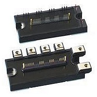
MOD IPM L-SER 7PAC 1200V 25A
Manufacturer
Powerex Inc
Series
Intellimod™r
Type
IGBTr
Datasheet
1.PM25RLB120.pdf
(6 pages)
Specifications of PM25RLB120
Configuration
3 Phase Inverter
Current
25A
Voltage
1200V
Voltage - Isolation
2500VDC
Package / Case
Module
Power Dissipation Pd
116W
Collector Emitter Voltage V(br)ceo
1.2kV
Continuous Collector Current Ic
25A
Collector Emitter Saturation Voltage Vce(sat)
2.3V
Output Current
25A
Leaded Process Compatible
Yes
Operating Voltage
1.2kV
Rohs Compliant
Yes
Circuit Configuration
7-Pac
Package
120x55mm - B
Recommended Accessory
BP7B-LS
Lead Free Status / RoHS Status
Lead free / RoHS Compliant
For Use With
BP7B-LS - KIT DEV INTERFACE FOR IPMBP7A-LS - KIT DEV INTERFACE FOR IPM
Lead Free Status / RoHS Status
Lead free / RoHS Compliant, Lead free / RoHS Compliant
Available stocks
Company
Part Number
Manufacturer
Quantity
Price
Company:

Part Number:
PM25RLB120
Manufacturer:
MITS
Quantity:
1 000
Part Number:
PM25RLB120
Manufacturer:
MITSUBISHI/三菱
Quantity:
20 000
Part Number:
PM25RLB120
Quantity:
60


4
Powerex, Inc., 200 E. Hillis Street, Youngwood, Pennsylvania 15697-1800 (724) 925-7272
PM25RLB120
Intellimod™ L-Series
Three Phase IGBT Inverter + Brake
25 Amperes/1200 Volts
Electrical and Mechanical Characteristics, T
Characteristics
Thermal Characteristics, T
Characteristic
Junction to Case Thermal Resistance
Inverter Part
Junction to Case Thermal Resistance
Brake Part
Contact Thermal Resistance
Recommended Conditions for Use
Characteristic
Supply Voltage
Control Supply Voltage*
Input ON Voltage
Input OFF Voltage
PWM Input Frequency
Arm Shoot-through Blocking Time
* With ripple satisfying the following conditions: dv/dt swing ≤ ±5V/µs, Variation ≤ 2V peak to peak.
30
20
10
0
0
COLLECTOR-EMITTER VOLTAGE, V
T
j
= 25°C
OUTPUT CHARACTERISTICS
(TYPICAL - INVERTER PART)
0.5
1.0
V
D
= 17V
1.5
CE
, (VOLTS)
15
j
= 25°C unless otherwise specified
13
2.0
R
R
V
V
R
R
Symbol
Symbol
R
Symbol
t
th(j-c)D
th(j-c)D
CIN(on)
CIN(off)
f
th(j-c)Q
th(j-c)Q
DEAD
V
PWM
th(c-f)
V
CC
D
2.0
1.5
1.0
0.5
0
SATURATION VOLTAGE CHARACTERISTICS
0
V
D
j
COLLECTOR-CURRENT, I
= 15V
= 25°C unless otherwise specified
(TYPICAL - INVERTER PART)
V
T
T
P
j
j
COLLECTOR-EMITTER
= 25°C
= 125°C
-V
V
VP1
VPC
10
Applied across P-N Terminals
Applied between V
Applied between U
-V
Thermal Grease Applied
Case to Fin Per Module,
, W
FWDi (Per 1/6 Module)
IGBT (Per 1/6 Module)
VPC
P
Test Conditions
-V
, V
Input Signal
C
Condition
Condition
WPC
20
, (AMPERES)
WP1
FWDi
IGBT
—
, U
-V
N
WPC
UP1
- V
P
30
-V
N
, V
-V
- W
UPC
UPC
N1
N
-V
,
-Br-V
,
NC
2.0
1.5
1.0
0.5
NC
COLLECTOR-EMITTER SATURATION VOLTAGE
0
12
VS. SUPPLY VOLTAGE CHARACTERISTICS
Min.
Min.
—
—
—
—
—
13
(TYPICAL - INVERTER PART)
SUPPLY VOLTAGE, V
14
Typ.
Typ.
—
—
—
—
—
15
15.0 ± 1.5
I
C
D
0.038
Value
≤800
16
, (VOLTS)
Max.
Max.
≤0.8
≥9.0
≥2.5
0.83
1.36
0.96
1.82
≤20
= 150A
T
T
j
j
= 25°C
= 125°C
17
°C/Watt
°C/Watt
°C/Watt
°C/Watt
°C/Watt
Volts
Volts
Volts
Volts
Units
Units
Units
kHz
18
µs
Related parts for PM25RLB120
Image
Part Number
Description
Manufacturer
Datasheet
Request
R

Part Number:
Description:
Power Module Power Modules Standard Power - Switchbox Ac/dc . Switchbox Pm25 Series Dc-dc Converter
Manufacturer:
Powerbox
Datasheet:
Part Number:
Description:
25-28 WATTS SINGLE & MULTIPLE OUTPUT AC/DC MEDICAL
Manufacturer:
POWERBOX [Powerbox]
Datasheet:

Part Number:
Description:
Manufacturer:
Powerex Inc
Datasheet:
Part Number:
Description:
Manufacturer:
Powerex Inc
Datasheet:
Part Number:
Description:
Manufacturer:
Powerex Inc
Datasheet:
Part Number:
Description:
Manufacturer:
Powerex Inc
Datasheet:
Part Number:
Description:
Manufacturer:
Powerex Inc
Datasheet:
Part Number:
Description:
Manufacturer:
Powerex Inc
Datasheet:
Part Number:
Description:
Manufacturer:
Powerex Inc
Datasheet:
Part Number:
Description:
Manufacturer:
Powerex Inc
Datasheet:
Part Number:
Description:
Manufacturer:
Powerex Inc
Datasheet:
Part Number:
Description:
Manufacturer:
Powerex Inc
Datasheet:
Part Number:
Description:
Manufacturer:
Powerex Inc
Datasheet:
Part Number:
Description:
Manufacturer:
Powerex Inc
Datasheet: