CM100TU-12F Powerex Inc, CM100TU-12F Datasheet - Page 3
CM100TU-12F
Manufacturer Part Number
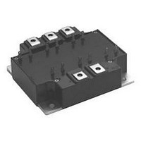
CM100TU-12F
Description
IGBT MOD 6PAC 600V 100A F SER
Manufacturer
Powerex Inc
Series
IGBTMOD™r
Datasheet
1.CM100TU-12F.pdf
(4 pages)
Specifications of CM100TU-12F
Configuration
Three Phase Inverter
Voltage - Collector Emitter Breakdown (max)
600V
Vce(on) (max) @ Vge, Ic
2.2V @ 15V, 100A
Current - Collector (ic) (max)
100A
Current - Collector Cutoff (max)
1mA
Input Capacitance (cies) @ Vce
27nF @ 10V
Power - Max
350W
Input
Standard
Ntc Thermistor
No
Mounting Type
Chassis Mount
Package / Case
Module
Collector Emitter Voltage Vces
600V
Continuous Collector Current Ic
100A
Collector Emitter Saturation Voltage Vce(sat)
1.6V
Current Rating
100A
Leaded Process Compatible
Yes
Voltage Rating
600V
Lead Free Status / RoHS Status
Lead free / RoHS Compliant
Igbt Type
-
Lead Free Status / RoHS Status
Lead free / RoHS Compliant, Lead free / RoHS Compliant
Available stocks
Company
Part Number
Manufacturer
Quantity
Price
Company:

Part Number:
CM100TU-12F
Manufacturer:
MITSUBISHI
Quantity:
26
Part Number:
CM100TU-12F
Manufacturer:
MITSUBISHI/三菱
Quantity:
20 000
Part Number:
CM100TU-12F
Quantity:
55


Powerex, Inc., 200 Hillis Street, Youngwood, Pennsylvania 15697-1800 (724) 925-7272
CM100TU-12F
Trench Gate Design Six IGBTMOD™
100 Amperes/600 Volts
Dynamic Electrical Characteristics, T
Characteristics
Input Capacitance
Output Capacitance
Reverse Transfer Capacitance
Inductive
Load
Switch
Times
Diode Reverse Recovery Time**
Diode Reverse Recovery Charge**
Thermal and Mechanical Characteristics, T
Characteristics
Thermal Resistance, Junction to Case
Thermal Resistance, Junction to Case
Thermal Resistance, Junction to Case
Contact Thermal Resistance
** Represents characteristics of the anti-parallel, emitter-to-collector free-wheel diode (FWDi).
Turn-on Delay Time
Rise Time
Turn-off Delay Time
Fall Time
R
R
R
R
th(j-c)
t
t
th(j-c)
th(j-c)
C
Symbol
C
Symbol
C
d(on)
d(off)
th(c-f)
Q
j
t
oes
res
t
t
ies
rr
= 2 5 C unless othe rwise specified
r
f
rr
'Q
Q
D
j
= 2 5 C unless otherwise specified
Per Module, Thermal Grease Applied
Per FWDi 1/6 Module, T
Per IGBT 1/6 Module, T
T
c
Point per Outline Drawing
Point per Outline drawing
Reference Point Under Chip
V
Per IGBT 1/6 Module,
V
CC
V
Switching Operation
CE
GE1
Inductive Load
= 300V, I
= 10V, V
R
Test Conditions
Test Conditions
I
E
= V
G
= 100A
= 6.3 ,
GE2
C
GE
= 15V,
= 100A,
c
= 0V
c
Reference
Reference
–
–
–
–
–
–
–
–
–
–
–
–
–
Min.
Min.
–
–
–
–
–
–
–
–
1.9
–
0.23
0.018
Typ.
Typ.
100
300
250
150
27
80
1.8
1
–
0.35
0.70
–
Max.
Max.
C/W
C/W
C/W
C/W
ns
ns
ns
ns
ns
nf
nf
nf
C
Units
Units
3
Related parts for CM100TU-12F
Image
Part Number
Description
Manufacturer
Datasheet
Request
R

Part Number:
Description:
IGBT MOD 6PAC 600V 100A U SER
Manufacturer:
Powerex Inc
Datasheet:

Part Number:
Description:
IGBT MOD 6PAC 1200V 100A F SER
Manufacturer:
Powerex Inc
Datasheet:
Part Number:
Description:
IGBT MOD 6PAC 1200V 100A U SER
Manufacturer:
Powerex Inc
Datasheet:


Part Number:
Description:
RF Devices / Rectifier Diodes
Manufacturer:
Bharat Electronics Ltd
Part Number:
Description:
Molded Mini-dyad
Manufacturer:
ETC-unknow
Datasheet:
Part Number:
Description:
Plug Connector
Manufacturer:
DDK Ltd.
Datasheet:
Part Number:
Description:
Molded Mini-DYAD
Manufacturer:
CLARE [Clare, Inc.]
Datasheet:
Part Number:
Description:
One-Touch Locking Style Small Sized Circular Connectors
Manufacturer:
DDK [DDK Ltd.]
Datasheet:

Part Number:
Description:
INDUCTOR CHIP SMD
Manufacturer:
Bourns Inc.
Datasheet:
Part Number:
Description:
INDUCTOR CHIP SMD
Manufacturer:
Bourns Inc.
Datasheet:
Part Number:
Description:
INDUCTOR CHIP SMD
Manufacturer:
Bourns Inc.
Datasheet:
Part Number:
Description:
INDUCTOR CHIP SMD
Manufacturer:
Bourns Inc.
Datasheet:
Part Number:
Description:
INDUCTOR CHIP SMD
Manufacturer:
Bourns Inc.
Datasheet: