IXSN80N60BD1 IXYS, IXSN80N60BD1 Datasheet
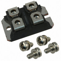
IGBT 600V SCSOA SOT-227B

IXSN80N60BD1

Manufacturer Part Number
IXSN80N60BD1
Description
IGBT 600V SCSOA SOT-227B
Manufacturer
IXYS
Datasheet

Specifications of IXSN80N60BD1

Configuration
Single
Voltage - Collector Emitter Breakdown (max)
600V
Vce(on) (max) @ Vge, Ic
2.5V @ 15V, 80A
Current - Collector (ic) (max)
160A
Current - Collector Cutoff (max)
200µA
Input Capacitance (cies) @ Vce
6.6nF @ 25V
Power - Max
420W
Input
Standard
Ntc Thermistor
No
Mounting Type
Chassis Mount
Package / Case
SOT-227, miniBLOC
Channel Type
N
Collector-emitter Voltage
600V
Gate To Emitter Voltage (max)
±20V
Mounting
Screw
Operating Temperature (min)
-55
Operating Temperature (max)
150C
Operating Temperature Classification
Military
Vces, (v)
600
Ic25, Tc=25°c, Igbt, (a)
100
Ic90, Tc=90°c, Igbt, (a)
80
Vce(sat), Max, Tj=25°c, Igbt, (v)
2.5
Tfi, Typ, Igbt, (ns)
180
Eoff, Typ, Tj=125°c, Igbt, (mj)
10
Rthjc, Max, Igbt, (k/w)
0.3
Package Style
SOT-227B
Lead Free Status / RoHS Status
Lead free / RoHS Compliant
Igbt Type
-
Lead Free Status / Rohs Status
Compliant

Available stocks

Company
Part Number
Manufacturer
Quantity
Price
Part Number:
IXSN80N60BD1
Manufacturer:
VICOR
Quantity:
560
IGBT with Diode
Short Circuit SOA Capability
© 2004 IXYS All rights reserved
Preliminary Data Sheet
Symbol
V
V
V
V
I
I
I
I
SSOA
(RBSOA)
t
(SCSOA)
P
V
T
T
T
M
Weight
Symbol
B V
V
I
I
V
IXYS reserves the right to change limits, test conditions and dimensions.
C25
L
C90
C M
S C
C E S
G E S
GEM
CE(sat)
s t g
C G R
J
J M
G E ( t h )
C E S
G E S
C
I S O L
d
C E S
Test Conditions
T
T
Continuous
Transient
T
Lead current limit (RMS)
T
T
V
Clamped inductive load
V
R
T
50/60 Hz
I
Mounting torque
Test Conditions
I
I
V
V
V
I
C
C
C
ISOL
C
C
C
C
J
J
GE
GE
CE
GE
CE
G
= 22 Ω, non repetitive
= 25°C to 150°C
= 25°C to 150°C; R
= 25°C (Silicon chip capability)
= 90°C
= 25°C, 1 ms
= 15 V, T
= 15 V, V
= 25°C
≤ 1 mA
= 500 µA, V
= 8 mA, V
= V
= 0 V
= 0 V, V
= I
C90
CES
, V
GE
GE
VJ
CE
CE
= 15 V; Note 1
= 125°C, R
= ±20 V
= 360 V, T
GE
= V
= 0 V
GE
t = 1 min
t = 1 s
GE
= 1 MΩ
J
G
= 125°C
= 5 Ω
T
T
(T
J
J
= 25°C
= 125°C
J
= 25°C, unless otherwise specified)
IXSN 80N60BD1 V
Characteristic Values
min.
600
4
-55 ... +150
-55 ... +150
Maximum Ratings
@ 0.8 V
I
CM
typ. max.
= 160
2500
3000
0.4/6 Nm/lb.in.
600
600
±20
±30
160
100
300
420
150
80
CES
30
10
G
E
±200
200
2.5
8
2
mA
V~
V~
µA
nA
C
°C
°C
°C
E
µs
V
V
V
W
V
A
V
V
A
A
A
A
A
g
miniBLOC, SOT-227 B
E = Emitter
G = Gate,
Main or Kelvin Emitter
Features
Applications
Advantages
I
V
t
C25
fi
International standard package
Aluminium-nitride isolation
- high power dissipation
Isolation voltage 3000 V~
UL registered E 153432
Low V
- for minimum on-state conduction
Fast Recovery Epitaxial Diode
- short t
Low collector-to-case capacitance
(< 60 pF)
- reduced RFI
Low package inductance (< 10 nH)
- easy to drive and to protect
Space savings
AC motor speed control
DC servo and robot drives
DC choppers
Uninterruptible power supplies (UPS)
Switch-mode and resonant-mode
power supplies
Easy to mount with 2 screws
High power density
Either Emitter terminal can be used as
CES
CE(sat)
losses
E153432
CE(sat)
G
rr
and I
,
= 600 V
= 160 A
= 2.5 V
= 180 ns
C = Collector
E = Emitter
RM
E
C
DS98890A(05/04)
E

Related parts for IXSN80N60BD1

IXSN80N60BD1 Summary of contents

Page 1

... CES ± Note 1 CE(sat) C C90 GE IXYS reserves the right to change limits, test conditions and dimensions. © 2004 IXYS All rights reserved IXSN 80N60BD1 Maximum Ratings 600 = 1 MΩ 600 GE ±20 ±30 160 100 80 300 = 5 Ω 160 0.8 V CES = 125° 420 ...

Page 2

... Note: 2. Remarks: Switching times may increase for V (Clamp) > 0.8 • higher T CE CES IXYS reserves the right to change limits, test conditions, and dimensions. IXYS MOSFETs and IGBTs are covered by one or more of the following U.S. patents: Characteristic Values (T = 25°C, unless otherwise specified) J min ...

Page 3

... V - Volts CE Fig. 5. Collector-to-Em itter Voltage vs . Gate-to-Em iiter voltage 160A Volts G E © 2004 IXYS All rights reserved 300 270 240 210 180 150 120 9V 7V 1.8 2.1 2.4 2.7 3 1.6 1.5 1.4 1.3 1.2 9V 1.1 1.0 0.9 7V 0.8 0.7 1.8 2 ...

Page 4

... C 225 200 I = 40A C 175 150 125 100 Ohms G IXYS reserves the right to change limits, test conditions, and dimensions. IXYS MOSFETs and IGBTs are covered by one or more of the following U.S. patents 200 240 280 320 120 140 160 G 275 250 225 ...

Page 5

... C 150 125 100 Degrees Centigrade J Fig. 15. Capacitance 10000 MHz 1000 100 Volts C E 1.0 0.1 0.0 1 © 2004 IXYS All rights reserved 160A 40A 160A 105 115 125 C ies C oes C res Fig. 16. Maxim um Transient Therm al Resistance 10 Pulse Width - milliseconds IXSN 80N60BD1 Fig ...

Page 6

... Z thJC 0.01 0.001 0.0001 0.00001 0.0001 0.001 Fig. 7 Transient thermal resistance junction to case IXYS reserves the right to change limits, test conditions, and dimensions. IXYS MOSFETs and IGBTs are covered by one or more of the following U.S. patents: 4000 T = 100° 300V nC R 3000 ...

Related keywords