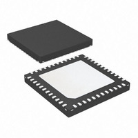
ATA5279P-PLPW Atmel, ATA5279P-PLPW Datasheet - Page 34

ATA5279P-PLPW
Manufacturer Part Number
ATA5279P-PLPW
Description
IC ANTENNA DVR SIX-FOLD 48VQFN
Manufacturer
Atmel
Datasheet
1.ATA5279P-PLQW.pdf
(40 pages)
Specifications of ATA5279P-PLPW
Rf Type
PEG, TPMS
Frequency
125kHz
Features
RSSI Equipped
Package / Case
48-VFQFN Exposed Pad
Lead Free Status / RoHS Status
Lead free / RoHS Compliant
8. Functional Parameters (Continued)
All parameters valid for 7.0V VS 16.5V and –40°C T
34
*) Type means: A = 100% tested, B = 100% correlation tested, C = Characterized on samples, D = Design parameter
Notes:
5.10
5.11
No.
5.1
5.2
5.3
5.4
5.5
5.6
5.7
5.8
5.9
6.1
6.2
6.3
6.4
6.5
6.6
5
6
1. In this column, pin group names are given. Please refer to
2. Operation of coils with higher impedance than the given value is possible but functional limitations might occur (inability to
Parameters
Low Current Driver Stage (A4P, A5P, A6P)
Sourcing current limit
(RMS)
Sinking current limit
(RMS)
Signal difference carrier
to harmonics 2, 3, 4, 5
Load imped. range
(amount of complex
impedance)
Min. output voltage
Max. output voltage
Idle mode cross current V
Idle mode output
voltage
Inactive pull-up current
Diagnosis mode pull-up
current
Diagnosis mode
pull-down current
Coil Return Line and Diagnosis Stage (A1N … A6N)
Return line switch
on-state resistance
Return line switch
overcurrent shutdown
threshold
Diagnosis mode pull-up
current
Diagnosis mode
pull-down current
Overtemperature
shutdown threshold
Open load and short
circuit detection AxN to
GND
Atmel ATA5279
more details.
reach to configured coil current). Coils with lower impedance should not be used as they might be detected as faulty.
(2)
Test Conditions
Idle mode, DC ramping
Idle mode, DC ramping
V
I
f
I
T
I
T
V
I
I
T
V
I
T
V
V
V
V
I
I
R
Ch. 1-3 selected
Ch. 4-6 selected
V
V
V
V
coil,p
OSCI
AxP
AxP
AxP
AxP
AxP
HPS
LPS
AxP,pp
j
j
j
j
AxP
AxP
AxP/N
AxP/N
VDS
VDS
VDS
VDS
VDS
Shunt
VDS
VDS
= 200mA
= –200mA
= 0
= ±200mA
= –100µA
= 0.22A
= 0.3A
= 0V
= 16.5V
= 200mA
= 8MHZ
30°C
30°C
= 16.5V
= 20V
30°C
= 20V
30°C
= 16.5V
= 16.5V
= 16.5V
= 16.5V
= 1
= 0V
= 16.5V
= 30V
a
105°C unless otherwise noted.
HDL
HDL
HDL
HDL
HRL
RLO
HRL
HRL
HRL
LDL
LDL
LDL
LDL
LRL
LDL
LDL
LDL
LDL
LRL
LRL
LRL
LRL
Pin
DS
R
R
Symbol
V
R
I
V
V
I
T
Section 2. “Pin Configuration” on page 2
I
Shunt,max
I
Z
I
I
I
I
DS,onHPS
LP,HSCL
AxPL,CC
DS,onLPS
LP,LSCL
AxPL,dile
PU,Diag
PD,Diag
PU,Diag
PD,Diag
OLP,max
AxPL,PU
t
OLP,min
OTsdwn
D
Coil,LP
OLdet
Sig
VDS – 4.5
0.875
–150
–150
Min.
–1.2
11.5
1.25
170
170
145
115
0.9
2.5
10
28
9
Typ.
40
VDS –
–0.55
1.225
Max.
–100
–100
1.05
1.75
–34
260
260
170
215
1.7
4.3
2.5
1.2
25
53
11
27
in this document for
Unit
mA
dB
µA
µA
µA
µA
k
°C
µs
A
A
V
V
V
A
A
9125L–RKE–03/11
Type*
D
B
B
A
A
A
A
A
B
A
A
A
A
A
A
B
A


