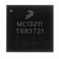
MC13211 Freescale Semiconductor, MC13211 Datasheet - Page 36

MC13211
Manufacturer Part Number
MC13211
Description
IC TXRX RF 2.4GHZ FLSH 16K 71LGA
Manufacturer
Freescale Semiconductor
Series
MC1321xr
Datasheet
1.1321XCSK-BDM.pdf
(70 pages)
Specifications of MC13211
Frequency
2.4GHz
Data Rate - Maximum
250kbps
Modulation Or Protocol
802.15.4 Zigbee
Applications
General Purpose
Power - Output
3dBm
Sensitivity
-92dBm
Voltage - Supply
1.8 V ~ 3.6 V
Current - Receiving
42mA
Current - Transmitting
35mA
Data Interface
PCB, Surface Mount
Memory Size
16kB Flash, 1kB RAM
Antenna Connector
PCB, Surface Mount
Operating Temperature
-40°C ~ 85°C
Package / Case
71-LGA
Mounting Style
SMD/SMT
Lead Free Status / RoHS Status
Lead free / RoHS Compliant
Available stocks
Company
Part Number
Manufacturer
Quantity
Price
Part Number:
MC13211
Manufacturer:
FREESCALE
Quantity:
20 000
5.7.4
The HCS08 includes two independent Timer/PWM (TPM) modules which support traditional input
capture, output compare, or buffered edge-aligned pulse-width modulation (PWM) on each channel. A
control bit in each TPM configures all channels in that timer to operate as center-aligned PWM functions.
In each of these two TPMs, timing functions are based on a separate 16-bit counter with prescaler and
modulo features to control frequency and range (period between overflows) of the time reference. This
timing system is ideally suited for a wide range of control applications, and the center-aligned PWM
capability on the 3-channel TPM extends the field of applications to motor control in small appliances.
The use of the fixed system clock, XCLK, as the clock source for either of the TPM modules allows the
TPM prescaler to run using the oscillator rate divided by two (ICGERCLK/2). This clock source must be
selected only if the ICG is configured in either FBE or FEE mode. In FBE mode, this selection is redundant
because the BUSCLK frequency is the same as XCLK. In FEE mode, the proper conditions must be met
for XCLK to equal ICGERCLK/2. Selecting XCLK as the clock source with the ICG in either FEI or SCM
mode will result in the TPM being non-functional.
5.7.4.1
The timer system in the MC1321x family MCU includes a one external 4-channel (5-channel internal)
TPM1 and one external 1-channel (3-channel internal) TPM2. Timer system features include
5.7.4.2
The TPM uses one input/output (I/O) pin per channel, TPMxCHn where x is the TPM number (for
example, 1 or 2) and n is the channel number (for example, 1–4). The TPM shares its I/O pins with
general-purpose I/O port pins.
one TPM, with various numbers of channels.
36
•
•
•
•
•
•
•
•
A total of 5 external channels:
— Each channel may be input capture, output compare, or buffered edge-aligned PWM
— Rising-edge, falling-edge, or any-edge input capture trigger
— Set, clear, or toggle output compare action
— Selectable polarity on PWM outputs
Each TPM may be configured for buffered, center-aligned pulse-width modulation (CPWM) on all
channels
Clock source to prescaler for each TPM is independently selectable as bus clock, fixed system
clock, or an external pin
Prescale taps for divide by 1, 2, 4, 8, 16, 32, 64, or 128
16-bit free-running or up/down (CPWM) count operation
16-bit modulus register to control counter range
Timer system enable
One interrupt per channel plus terminal count interrupt
Timer/PWM (TPM) Module Introduction
TPM Features
TPM Block Diagram
Figure 21
MC13211/212/213 Technical Data, Rev. 1.8
shows the structure of a TPM. Some MCUs include more than
Freescale Semiconductor


