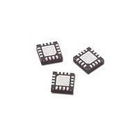
IAM-92516-TR2 Avago Technologies US Inc., IAM-92516-TR2 Datasheet - Page 2

IAM-92516-TR2
Manufacturer Part Number
IAM-92516-TR2
Description
IC RF GAAS FET MIXER 16-LPCC
Manufacturer
Avago Technologies US Inc.
Datasheet
1.IAM-92516-TR2.pdf
(7 pages)
Specifications of IAM-92516-TR2
Package / Case
16-VFQFN Exposed Pad
Number Of Mixers
1
Noise Figure
12.5dB
Current - Supply
26mA
Voltage - Supply
10 V
Maximum Input Frequency
3500 MHz
Mounting Style
SMD/SMT
Maximum Operating Frequency
300 MHz
Maximum Power Gain
6.9 dB
Operating Supply Voltage
10 V
Output Frequency
300MHz
Lead Free Status / RoHS Status
Lead free / RoHS Compliant
Frequency
-
Rf Type
-
Gain
-
Secondary Attributes
-
Lead Free Status / Rohs Status
Compliant
2
IAM-92516 Absolute Maximum Ratings
Parameter
Device Voltage
CW RF Input Power
CW LO Input Power
Channel Temperature
Storage Temperature
Electrical Specifications
T
Symbol
F
F
F
Id
G
IIP3
NF
P1dB
RL
RL
RL
ISOL
ISOL
ISOL
Notes:
1. Standard deviation number is based on measurement of at least 500 parts from three non-consecutive wafer lots during the initial characterization of
2. IIP3 test condition: F
3. Conversion loss, P1dB and NF data have de-embedded balun loss = 0.8 dB @ 210 MHz.
Simplified Schematic
RF
LO
IF
A
c
[3]
RF
LO
IF
[3]
= 25°C, DC =5V @ 26 mA, RF =1.91 GHz, Pin
[2]
this product and is intended to be used as an estimate for distribution of the typical specification.
L-R
L-I
R-L
[3]
[2]
[2]
Parameter and Test Condition
Frequency Range, RF
Frequency Range, LO
Frequency Range, IF
Device Current
Conversion Loss
Input Third Order Intercept Point
SSB Noise Figure
Output Power at 1 dB Compression
RF Port Return Loss
LO Port Return Loss
IF Port Return Loss
LO-RF Isolation
LO-IF Isolation
RF-IF Isolation
RF1
= 1.91 GHz, F
Units
V
dBm
dBm
°C
°C
RF2
= 1.89 GHz with input power of -10 dBm per tone and LO power = -3 dBm at LO frequency F
RF
= -10 dBm; LO =1.7 GHz, Pin
[1]
Figure 1. IAM-92516 Test Board.
Absolute Max.
10
+30
20
150
-65 to 150
LO
= -3 dBm, IF = 210 MHz unless otherwise specified.
Units
MHz
MHz
MHz
dB
dB
dBm
mA
dBm
dB
dB
dB
dB
dB
dB
Min.
400
22
400
DC
22
Thermal Resistance
θ
Notes:
1. Operation of this device above any one of these
2. Assuming DC quiescent conditions and
3. Board (package belly) temperature T
4. Channel-to-board thermal resistance
ch-c
parameters may cause permanent damage.
T
25°C. Derate 21 mW/°C for T
measured using 150°C Liquid Crystal
Measurement method.
A
= 25°C.
Typ.
26
6
27
12.5
9
19
24
21
34
56
33
= 47.6°C/W
Max.
3500
3500
300
30
6.9
[2,4]
LO
= 1.7 GHz.
B
> 85°C.
Std Dev.
0.89
0.08
0.43
B
is
[1]


