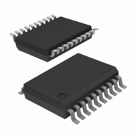
SA676DK/01,118 NXP Semiconductors, SA676DK/01,118 Datasheet - Page 6

SA676DK/01,118
Manufacturer Part Number
SA676DK/01,118
Description
IC MIXER FM IF SYSTEM LV 20-SSOP
Manufacturer
NXP Semiconductors
Series
SA676r
Datasheet
1.SA676DK01118.pdf
(22 pages)
Specifications of SA676DK/01,118
Package / Case
20-SSOP
Rf Type
Cordless Phones
Frequency
100MHz
Number Of Mixers
2
Gain
17dB
Noise Figure
7dB
Secondary Attributes
Up Converter
Current - Supply
5mA
Voltage - Supply
2.7 V ~ 7 V
Maximum Input Frequency
100 MHz
Mounting Style
SMD/SMT
Maximum Power Gain
17 dB
Operating Supply Voltage
3 V
Maximum Operating Temperature
+ 85 C
Minimum Operating Temperature
- 40 C
Operating Temperature (min)
-40C
Operating Temperature (max)
85C
Operating Temperature Classification
Industrial
Lead Free Status / RoHS Status
Lead free / RoHS Compliant
Lead Free Status / RoHS Status
Lead free / RoHS Compliant, Lead free / RoHS Compliant
Other names
568-2037-2
935275291118
SA676DK/01-T
935275291118
SA676DK/01-T
NXP Semiconductors
11. Dynamic characteristics
Table 6.
T
IF frequency = 455 kHz; R17 = 2.4 k
deviation. Audio output with de-emphasis filter and C-message weighted filter. Test circuit
below are tested using automatic test equipment to assure consistent electrical characteristics. The limits do not represent
the ultimate performance limits of the device. Use of an optimized RF layout will improve many of the listed parameters.
[1]
SA676
Product data sheet
Symbol
Mixer/oscillator section (external LO = 220 mV RMS value)
f
f
NF
IP3
G
R
C
R
IF section
G
G
α
V
SINAD
THD
S/N
V
α
Z
Z
Z
Z
V
RF/IF section (internal LO)
SINAD
i
osc
amb
AM
RSSI(range)
i(IF)
o(IF)
i(lim)
o(lim)
o(aud)
o(RSSI)
o(RMS)
i(RF)
i(RF)
o(mix)
p(conv)
amp(IF)
lim
I
The generator source impedance is 50 Ω, but the SA676 input impedance at IF_AMP_IN (pin 18) is 1500 Ω. As a result, IF level refers
to the actual signal that enters the SA676 input (IF_AMP_IN, pin 18), which is about 21 dB less than the ‘available power’ at the
generator.
= 25
°
C; V
Dynamic characteristics
signal-to-noise-and-distortion ratio IF level −110 dBm
signal-to-noise ratio
signal-to-noise-and-distortion ratio system; RF level = −114 dBm
Parameter
input frequency
oscillator frequency
noise figure
input third-order intercept point
conversion power gain
RF input resistance
RF input capacitance
mixer output resistance
IF amplifier gain
limiter gain
AM rejection
audio output voltage
total harmonic distortion
RSSI output voltage
RSSI range
IF input impedance
IF output impedance
limiter input impedance
limiter output impedance
RMS output voltage
CC
= 3 V; unless specified otherwise. RF frequency = 45 MHz + 14.5 dBV RF input step-up.
Ω
and R18 = 3.3 k
All information provided in this document is subject to legal disclaimers.
Conditions
at 45 MHz
50 Ω source;
f1 = 45.0 MHz; f2 = 45.06 MHz;
input RF level = −52 dBm
matched 14.5 dBV step-up
50 Ω source
single-ended input
MIXER_OUT pin
50 Ω source
50 Ω source
30 % AM 1 kHz
gain of two
no modulation for noise
IF; R9 = 2 kΩ
IF_AMP_IN pin
IF_AMP_OUT pin
LIMITER_IN pin
LIMITER_OUT pin
LIMITER_OUT pin
Rev. 2 — 12 April 2011
IF level = −110 dBm
IF level = −50 dBm
Ω
. RF level =
−
45 dBm; FM modulation = 1 kHz with
Low-voltage mixer FM IF system
[1]
Figure
-
-
10
-
-
-
1.3
Min
-
-
-
-
-
1.25
-
60
-
-
-
-
-
-
1.3
-
-
-
9. The parameters listed
Typ
100
100
7.0
−10
17
2.5
8
3.0
1.5
44
58
50
120
17
−55
60
0.5
1.7
70
1.5
0.3
1.5
0.3
130
12
© NXP B.V. 2011. All rights reserved.
±
5 kHz peak
SA676
-
-
-
-
-
4.0
-
-
-
-
0.9
2.2
-
-
-
-
Max
-
-
-
-
-
-
-
-
-
Unit
MHz
MHz
dB
dBm
dB
dB
kΩ
pF
kΩ
dB
dB
dB
mV
dB
dB
dB
V
V
dB
kΩ
kΩ
kΩ
kΩ
mV
dB
6 of 22


