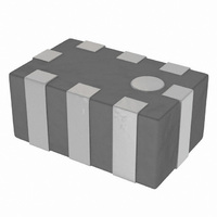
FI212P089213-T Taiyo Yuden, FI212P089213-T Datasheet - Page 4

FI212P089213-T
Manufacturer Part Number
FI212P089213-T
Description
FILTER DIPLEXER 892/1940MHZ SMD
Manufacturer
Taiyo Yuden
Datasheet
1.FI212B245027-T.pdf
(10 pages)
Specifications of FI212P089213-T
Featured Product
Multilayer Diplexers and Dual Low Pass Filters
Frequency Bands (low / High)
824MHz ~ 960MHz / 1.71GHz ~ 2.17GHz
Low Band Attenuation (min / Max Db)
13.00dB / -
High Band Attenuation (min / Max Db)
19.00dB / -
Return Loss (low Band / High Band)
9.5dB / 9.5dB
Mounting Type
Surface Mount
Package / Case
2012 (5030 Metric)
Filter Type
High Pass
Filter Case
0805
Termination Type
SMD
Rohs Compliant
Yes
Reel Quantity
3000
Filter Terminals
SMD
Lead Free Status / RoHS Status
Lead free / RoHS Compliant
Other names
587-2661-2
Available stocks
Company
Part Number
Manufacturer
Quantity
Price
Company:
Part Number:
FI212P089213-T
Manufacturer:
NXP
Quantity:
86
164
■
* This catalog contains the typical specification only due to the limitation of space. When you consider the purchase of our products, please check our specification.
For details of each product (characteristics graph, reliability information, precautions for use, and so on), see our Web site (http://www.ty-top.com/) or CD catalogs.
ELECTRICAL CHARACTERISTICS ・ TYPICAL CHARACTERISTICS
FI 212L062002
FI 212L062003
FI 212L062009
FI 168L062005
Pass band frequency 470 – 770 MHz
Insertion loss at
Insertion loss at
Insertion loss at
Ripple at 470 – 710 MHz 1.2 dB max.
V.S.W.R. at 470 – 710 MHz 2.0 max.
Attenuation
Impedance
Pass band frequency 470 – 770 MHz
Insertion loss at
Insertion loss at
Insertion loss at
Ripple at 470 – 710 MHz 1.2 dB max.
V.S.W.R. at 470 – 710 MHz 2.5 max.
Attenuation
Impedance
Pass band frequency 470 – 806 MHz
Insertion loss at
Insertion loss at
Insertion loss at
Ripple at 470 – 710 MHz 1.2 dB max.
V.S.W.R. at 470 – 710 MHz 2.2 max.
Attenuation
Impedance
Pass band frequency 470 – 770 MHz
Insertion loss at
Insertion loss at
Insertion loss at
Ripple at 470 – 710 MHz 1.4 dB max.
V.S.W.R.
Attenuation
Impedance
750 – 806 MHz
470 – 710 MHz
710 – 750 MHz
470 – 600MHz
600 – 710MHz
710 – 770MHz
470-600MHz
470-600MHz
600-710MHz
710-770MHz
600-710MHz
710-770MHz
(25 deg-C)
(-30~+85 deg-C)
(25 deg-C)
(-30~+85 deg-C)
(25 deg-C)
(-30~+85 deg-C)
0.9 dB max. (25 deg-C)
1.1 dB max. (-30~+85 deg-C)
1.5 dB max. (25 deg-C)
1.7 dB max. (-30~+85 deg-C)
3.4 dB max. (25 deg-C)
3.7 dB max. (-30~+85 deg-C)
25 dB min. (888 – 925 MHz)
25 dB min. (940 – 960 MHz)
27 dB min. (1429 – 1453 MHz)
26 dB min. (1920 – 1980 MHz)
26 dB min. (2400 – 2500 MHz)
50 ohm
0.7 dB max. (25 deg-C)
0.9 dB max. (-30~+85 deg-C)
1.5 dB max. (25 deg-C)
1.7 dB max. (-30~+85 deg-C)
3.3 dB max. (25 deg-C)
3.7 dB max. (-30~+85 deg-C)
15 dB min. (830 – 840 MHz)
11 dB min. (830 – 840 MHz)
15 dB min. (888 – 925 MHz)
15 dB min. (940 – 960 MHz)
7 dB min. (1429 – 1453 MHz)
8 dB min. (1920 – 1980 MHz)
8 dB min. (2400 – 2500 MHz)
50 ohm
1.6 dB max. (25 deg-C)
1.8 dB max. (-30~+85 deg-C)
2.2 dB max. (25 deg-C)
2.5 dB max. (-30~+85 deg-C)
5.2 dB max. (25 deg-C)
6.0 dB max. (-30~+85 deg-C)
20 dB min. (880 – 915 MHz)
17 dB min. (880 – 915 MHz)
30 dB min. (1710-1910 MHz)
50 ohm
1.2 dB max. (25 deg-C)
1.3 dB max. (-30~+85 deg-C)
2.2 dB max. (25 deg-C)
2.4 dB max. (-30~+85 deg-C)
4.0 dB max. (25 deg-C)
4.4 dB max. (-30~+85 deg-C)
2.0 max. (470 – 710 MHz)
2.5 max. (710 – 770 MHz)
25 dB min. (888 – 925 MHz)
21 dB min. (888 – 925 MHz)
25 dB min. (940 – 960 MHz)
27 dB min. (1429 – 1453 MHz)
26 dB min. (1920 – 1980 MHz)
26 dB min. (2400 – 2500 MHz)
50 ohm
-10
-20
-30
-40
-50
-10
-20
-30
-40
-50
0
0
0.0
0.0
1.0
1.0
1 1
2.0
2.0
3.0
3.0
4.0
4.0
5.0
5.0
6.0
6.0
S11
S21
FI 168D087018
FI 212C245032
FI 168L259764
7.0
7.0
S11
S21
8.0
8.0
Pass band frequency
Insertion loss at
Insertion loss at
Ripple at 470 – 770 MHz 0.3 dB max.
Ripple at 2300 – 2700 MHz 0.3 dB max.
V.S.W.R.at 470 – 770MHz
V.S.W.R.at 2300 – 2700MHz 2.0 max.
Attenuation
Impedance
Low band
Pass band frequency 824 – 915 MHz
Insertion loss at
824 – 915 MHz
V.S.W.R.
at 824 – 915 MHz
Attenuation
Impedance
High band
Pass band frequency 1710 – 1910 MHz
Insertion loss at
1710 – 1910 MHz
V.S.W.R.
at 824 – 915 MHz
Attenuation
Impedance
Isolation
In to In/Out to Out
In to Out
Pass band frequency 2400-2500MHz
Insertion loss at
pass band
Ripple at pass band 1.0 dB max.
Unbalanced port
V.S.W.R. at pass band
Balanced port V.S.W.R.
at pass band
Amplitude Imbalance
Phase Imbalance
Attenuation
Unbalanced Port
Impedance
Balanced Port
Impedance
at pass band
at pass band
2300-2700MHz
470-770MHz
470 – 770 MHz
2300 – 2700 MHz
0.5 dB max. (25 deg-C)
0.6 dB max. (-30~+85 deg-C)
0.5 dB max. (25 deg-C)
0.6 dB max. (-30~+85 deg-C)
2.0 max.
20 dB min. (4600 – 5400 MHz)
20 dB min. (6900 – 8100 MHz)
50 ohm
0.6 dB max. ( -20 to +85 Deg.C)
1.5 max.
25 dB min. (1648-1830MHz)
25 dB min. (2472-2745MHz)
50 ohm
0.6 dB max. ( -20 to +85 Deg.C)
1.5 max.
25 dB min. (3420-3820MHz)
25 dB min. (5130-5730MHz)
50 ohm
27 dB min. (824-915MHz)
30 dB min. (1710-1910MHz)
30 dB min. (824-915MHz)
30 dB min. (1710-1910MHz)
3.7 dB (25deg-C)
4.0 dB (-30~+85deg-C)
2.0 max.
2.0 max.
2.0 dB max.
180 +/- 10 deg
35 dB min. (880-960MHz)
20 dB min. (1710-1990MHz)
20 dB min. (1990-2170MHz)
20 dB min. (4800-5000MHz)
50 ohm
Conjugated match to CSR BC4
chipfilter01_e-01


