MSA-2111-BLKG Avago Technologies US Inc., MSA-2111-BLKG Datasheet
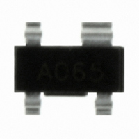
AMP MMIC SI BIPOLAR SOT-143

MSA-2111-BLKG

Manufacturer Part Number
MSA-2111-BLKG
Description
AMP MMIC SI BIPOLAR SOT-143
Manufacturer
Avago Technologies US Inc.
Datasheet

Specifications of MSA-2111-BLKG

Gain
16dB ~ 17.5dB
Current - Supply
40mA
Frequency
0Hz ~ 4GHz
Noise Figure
3.3dB
P1db
10dBm
Package / Case
SOT-143, SOT-143B, TO-253AA
Test Frequency
900MHz
Voltage - Supply
2.9V ~ 4.3V
Frequency Range
0.1GHz To 2.5GHz
Noise Figure Typ
3.3dB
Power Dissipation Pd
125mW
Supply Current
35mA
Supply Voltage Range
2.9V To 4.3V
Rf Type
General Purpose
Manufacturer's Type
MMIC Amplifier
Number Of Channels
1
Frequency (max)
4GHz
Operating Supply Voltage (min)
2.9V
Operating Supply Voltage (typ)
3.6V
Operating Supply Voltage (max)
4.3V
Package Type
SOT-143
Mounting
Surface Mount
Pin Count
3 +Tab
Noise Figure (typ)
3.3@900MHzdB
Lead Free Status / RoHS Status
Lead free / RoHS Compliant
Lead Free Status / RoHS Status
Lead free / RoHS Compliant, Lead free / RoHS Compliant
Other names
516-1970
MSA-2111-BLKG

Available stocks

Company
Part Number
Manufacturer
Quantity
Price
Part Number:
MSA-2111-BLKG
Manufacturer:
AVAGO/安华高
Quantity:
20 000
MSA-2111
Cascadable Silicon Bipolar MMIC Amplifier
Data Sheet
Description
The MSA-2111 is a low cost silicon bipolar Monolithic Mi-
crowave Integrated Circuit (MMIC) housed in a surface
mount plastic SOT-143 package. This MMIC is designed
for use as a general purpose 50 Ω gain block. Typical ap-
plications include narrow and broad band IF and RF am-
plifiers in commercial and industrial applications.
The MSA-series is fabricated using Avago’s 10 GHz f
25 GHz f
tride self-alignment, ion implantation, and gold metalli-
zation to achieve excellent performance, uniformity and
reliability. The use of an external bias resistor for temper-
ature and current stability also allows bias flexibility.
SOT-143 Package
Pin Connections and Package Marking
Notes:
Top View. Package Marking provides orientation and identification.
"x" is the date code.
A06x
MAX
, silicon bipolar MMIC process which uses ni-
T
,
Features
• High Gain: 16.5 dB Typical at 900 MHz
• Low Noise Figure:
• Low Cost Surface Mount Plastic Package
• Tape-and-Reel Packaging Option Available
Typical Biasing Configuration
IN
Cascadable 50 Ω Gain Block
Medium Power: 10 dBm at 900 MHz
3.3 dB Typical at 900 MHz
Lead-free Option Available
C
block
MSA
V
d
= 3.6 V
RFC (Optional)
R
C
bias
block
V
OUT
CC
>
5
V

Related parts for MSA-2111-BLKG

MSA-2111-BLKG Summary of contents

Page 1

... The MSA-2111 is a low cost silicon bipolar Monolithic Mi- crowave Integrated Circuit (MMIC) housed in a surface mount plastic SOT-143 package. This MMIC is designed for use as a general purpose 50 Ω gain block. Typical ap- plications include narrow and broad band IF and RF am- plifiers in commercial and industrial applications. The MSA-series is fabricated using Avago’s 10 GHz f 25 GHz f , silicon bipolar MMIC process which uses ni- MAX tride self-alignment, ion implantation, and gold metalli- zation to achieve excellent performance, uniformity and reliability. The use of an external bias resistor for temper- ature and current stability also allows bias flexibility ...

Page 2

... Group Delay D V Device Voltage d dV/dT Device Voltage Temperature Coefficient Notes: 1. The recommended operating current range for this device mA. Typical gain performance as a function of current is on the follow- ing page. Ordering Information Part Numbers No. of Devices MSA-2111-BLK 100 MSA-2111-BLKG 100 MSA-2111-TR1 3000 MSA-2111-TR1G 3000 MSA-2111-TR2 10000 MSA-2111-TR2G 10000 Note: Order part number with a “G” suffix if lead-free option is desired. 2 [1] Absolute Maximum 40 mA ...

Page 3

... MSA-2111 Typical Scattering Parameters ( Freq. GHz Mag Ang 0.1 .28 171 0.2 .26 163 0.3 .24 156 0.4 .21 152 0.5 .18 149 0.6 .15 148 0.7 .13 148 0.8 .11 152 0.9 .09 158 1.0 .07 169 1.5 .08 –123 2.0 .11 –124 2.5 .15 –167 3.0 .27 158 3.5 .38 145 4.0 .46 135 Typical Performance 25° ...

Page 4

SOT-143 Package Dimensions OUTPUT AND BIAS GROUND B1 XXX E E1 GROUND RF INPUT Notes: XXX-package marking Drawings are not to scale For product information and a complete list of distributors, please ...

Related keywords