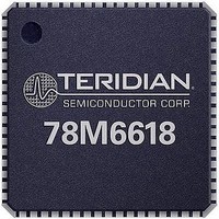
78M6618-IM/F Maxim Integrated Products, 78M6618-IM/F Datasheet - Page 2

78M6618-IM/F
Manufacturer Part Number
78M6618-IM/F
Description
IC PWR MEASUREMENT OCTAL 68-QFN
Manufacturer
Maxim Integrated Products
Type
Octal Power and Energy Measurement ICr
Datasheet
1.78M6618-IMF.pdf
(32 pages)
Specifications of 78M6618-IM/F
Core
80515
Core Architecture
80515
Data Bus Width
8 bit
Data Ram Size
4 KB
Interface Type
SPI, UART
Maximum Clock Frequency
500 KHz
Maximum Operating Temperature
+ 85 C
Minimum Operating Temperature
- 40 C
Mounting Style
SMD/SMT
Number Of Programmable I/os
19
Number Of Timers
1
On-chip Adc
21 bit, 10 Channel
Operating Supply Voltage
3.3 V
Package / Case
QFN-68
Processor Series
78M6618
Program Memory Size
128 KB
Program Memory Type
Flash
Lead Free Status / RoHS Status
Lead free / RoHS Compliant
Available stocks
Company
Part Number
Manufacturer
Quantity
Price
Company:
Part Number:
78M6618-IM/F
Manufacturer:
ATMEL
Quantity:
240
78M6618 Data Sheet
1
2
2
Hardware Functional Description...................................................................................................... 5
1.1
1.2
1.3
1.4
1.5
1.6
1.7
1.8
1.9
1.10 Oscillator ...................................................................................................................................... 9
1.11 PLL and Internal Clock Generation .............................................................................................. 9
1.12 Real-Time Clock (RTC) .............................................................................................................. 10
1.13 Hardware Watchdog Timer ........................................................................................................ 10
1.14 Temperature Sensor .................................................................................................................. 10
1.15 General Purpose Digital I/O ....................................................................................................... 10
1.16 LCD Drivers ............................................................................................................................... 11
1.17 EEPROM Interface .................................................................................................................... 11
1.18 SPI Slave Port ............................................................................................................................ 11
1.19 Test Port..................................................................................................................................... 12
1.20 UARTs ........................................................................................................................................ 13
1.21 In Circuit Emulator (ICE) Port .................................................................................................... 13
Electrical Specifications ................................................................................................................... 14
2.1
2.2
2.3
2.4
2.5
Hardware Overview ..................................................................................................................... 5
Device Reset ................................................................................................................................ 7
Power Management ..................................................................................................................... 7
Analog Front End (AFE) ............................................................................................................... 7
Digital Computation Engine (CE) ................................................................................................. 8
80515 MPU Core ......................................................................................................................... 8
XRAM ........................................................................................................................................... 9
IORAM ......................................................................................................................................... 9
FLASH .......................................................................................................................................... 9
Absolute Maximum Ratings ....................................................................................................... 14
Recommended External Components ....................................................................................... 15
Recommended Operating Conditions ........................................................................................ 15
Performance Specifications ....................................................................................................... 16
Timing Specifications ................................................................................................................. 22
1.3.1 Voltage Regulator ............................................................................................................ 7
1.3.2 Power Fault Management ................................................................................................ 7
1.3.3 BROWNOUT .................................................................................................................... 7
1.3.4 SLEEP mode ................................................................................................................... 7
1.4.1 Analog Current and Voltage Inputs ................................................................................. 8
1.6.1 SFR .................................................................................................................................. 9
1.9.1 Program Security ............................................................................................................. 9
1.20.1 UART1 (OPT_TX/OPT_RX) .......................................................................................... 13
2.4.1 Input Logic Levels .......................................................................................................... 16
2.4.2 Output Logic Levels ....................................................................................................... 16
2.4.3 Power-Fault Comparator ............................................................................................... 16
2.4.4 Battery Monitor............................................................................................................... 17
2.4.5 Supply Current ............................................................................................................... 17
2.4.6 V3P3D Switch ................................................................................................................ 17
2.4.7 2.5 V Voltage Regulator ................................................................................................. 18
2.4.8 Low-Power Voltage Regulator ....................................................................................... 18
2.4.9 Crystal Oscillator ............................................................................................................ 18
2.4.10 LCD DAC ....................................................................................................................... 18
2.4.11 LCD Drivers ................................................................................................................... 19
2.4.12 Optical Interface ............................................................................................................. 19
2.4.13 Temperature Sensor ...................................................................................................... 19
2.4.14 VREF ............................................................................................................................. 20
2.4.15 ADC Converter, V3P3A Referenced ............................................................................. 21
2.5.1 Flash Memory ................................................................................................................ 22
2.5.2 EEPROM Interface ........................................................................................................ 22
2.5.3 RESET ........................................................................................................................... 22
2.5.4 RTC ................................................................................................................................ 22
2.5.5 SPI Slave Port (MISSION Mode) ................................................................................... 23
Table of Contents
DS_6618_005
Rev. 1.4


