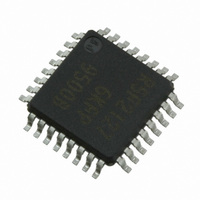
XR21V1414IM48-F Exar Corporation, XR21V1414IM48-F Datasheet - Page 14

XR21V1414IM48-F
Manufacturer Part Number
XR21V1414IM48-F
Description
IC UART FIFO USB QUAD 48TQFP
Manufacturer
Exar Corporation
Type
USB UARTsr
Datasheet
1.XR21V1414IM48-F.pdf
(32 pages)
Specifications of XR21V1414IM48-F
Package / Case
48-TQFP
Features
*
Number Of Channels
1, UART
Fifo's
128 Byte
Protocol
USB 2.0
Voltage - Supply
3.3V
With Auto Flow Control
Yes
Mounting Type
Surface Mount
Maximum Operating Temperature
+ 85 C
Minimum Operating Temperature
- 40 C
Mounting Style
SMD/SMT
Supply Current
16 mA
Operating Supply Voltage
2.97 V to 3.63 V
No. Of Channels
4
Data Rate
12Mbps
Uart Features
Automatic Hardware And Software Flow Control, Half-Duplex Mode, Fractional Baud Rate Generator
Supply Voltage Range
2.97V To 3.63V
Rohs Compliant
Yes
Lead Free Status / RoHS Status
Lead free / RoHS Compliant
For Use With
1016-1303 - EVAL BOARD FOR XR21V1414IM
Lead Free Status / Rohs Status
Lead free / RoHS Compliant
Other names
1016-1304
Available stocks
Company
Part Number
Manufacturer
Quantity
Price
Company:
Part Number:
XR21V1414IM48-F
Manufacturer:
EXAR
Quantity:
5 000
Company:
Part Number:
XR21V1414IM48-F
Manufacturer:
Exar Corporation
Quantity:
10 000
Part Number:
XR21V1414IM48-F
Manufacturer:
EXAR/艾科嘉
Quantity:
20 000
XR21V1414
4-CH FULL-SPEED USB UART
If an address match occurs in either flow control mode 3 or 4, the address byte will not be loaded into the RX
FIFO, but all subsequent data bytes will be loaded into the RX FIFO. The UART Receiver will automatically be
disabled when an address byte is received that does not match the values in the XON_CHAR or XOFF_CHAR
register.
In flow control mode 3, the UART transmitter is always enabled, irrespective of the Rx address match. In flow
control mode 4, the UART transmitter will only be enabled if there is an Rx address match.
By default, the GPIO5/RTS# pin will be de-asserted immediately after the stop bit of the last byte has been
shifted. However, this may not be ideal for systems where the signal needs to propagate over long cables.
Therefore, the de-assertion of GPIO5/RTS# pin can be delayed from 1 to 15 bit times via the
XCVR_EN_DELAY register to allow for the data to reach distant UARTs.
Half-duplex mode is enabled when FLOW_CONTROL[3] = 1. In this mode, the UART will ignore any data on
the RX input when the UART is transmitting data.
In normal operation all bulk-in transfers will be of maxPacketSize (64) bytes to improve throughput and to
minimize USB host processing. However, in cases where the baud rate is low this may increase latency
unacceptably. To compensate, the V1414 device has a low latency mode in which received data bytes will be
immediately forwarded at the next BULK_IN packet. The Low Latency mode will be automatically set from a
CDC_ACM_IF_SET_LINE_CODING command whenever the baud rate is less than 46921 bps or alternately a
custom driver may set the RX_FIFO_LOW_LATENCY register bit to force RX data to be delivered without
delay.
If the V1414 device has entered the Suspend state, the GPIO0/RI# pin of the Channel A UART can be used to
request that the host exit the Suspend state. A high to low transition on this pin will cause the device to signal a
remote wakeup request to the host via a custom driver. Note that the standard CDC-ACM driver does not
support this feature. In order for the remote wakeup to work, several things must be properly configured. First,
the GPIO0/RI# pin must be configured as an input. Additionally, the V1414 device must have the remote
wakeup feature support indicated in the USB attributes - See
the software driver must inform the USB host that the peripheral device supports the remote wake-up feature.
1.5.7.1
1.5.7.2
1.5.8
1.5.9
1.5.10
1.5.11
Programmable Turn-Around Delay
Half-Duplex Mode
RX FIFO Latency
Remote Wakeup
Receiver
Transmitter
14
“Section 1.3, I2C Interface” on page
10. Lastly,
REV. 1.1.0


