2891411 Phoenix Contact, 2891411 Datasheet - Page 13
2891411
Manufacturer Part Number
2891411
Description
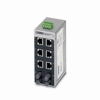
SWITCH ETHERNET 6/RJ45-2ST F/OPT
Manufacturer
Phoenix Contact
Type
Ethernetr
Specifications of 2891411
Features
6 Ports
Product
Switches
Usoc Codes
RJ45
Number Of Ports
6, 2
Gender
Female
Shielding
Shielded
Current Rating
230 mA
Voltage Rating
24 V
Housing Material
Aluminum
Contact Material
Copper Alloy
Contact Type
RJ45, Fiber Optic
Number Of Rows
2
Operating Temperature Range
0 C to + 60 C
Brand/series
SFN Series
Phoenix Part Number
FL SWITCH SFN 6TX/2FX ST
Primary Type
Switch
Protocol Type
Ethernet
Special Features
Auto Negotiation, Store and Forward
Transmission Speed
10/100 MBit/s
Lead Free Status / RoHS Status
Lead free / RoHS Compliant


Unidirectional data transfer guidelines
In applications where the data flow is predominantly in one
direction, such as cameras and vision systems, near 100%
loading is possible using jumbo frames.
Figure 12
When cascading devices in a trunk topology, up to 18 Mbps
of the available bandwidth is required to support overhead
and pause frame traffic for each link between cascaded
switches.
Figure 13
2732_en_A
1000
200
180
160
140
120
100
900
800
700
600
500
400
300
200
100
80
60
40
20
0
0
2000
2000
Maximum unidirectional traffic loading per port
(FL SWITCH SFN 8GT)
Overhead/cascaded switch vs. frame size
3000
3000
4000
4000
Frame size (bytes)
Frame size (bytes)
Maximum loading
Pause frame threshold
5000
5000
6000
6000
7000
7000
8000
8000
9000
9000
9600
9.4
Because of the buffer size considerations when using jumbo
frames, network bandwidth loading should be planned in
advance to prevent packet loss.
1.
Table 2
2.
3.
4.
60 frames per
second
750 x 640 pixels
per frame
Typical Camera
Determine the total application traffic load for the
connected devices.
Add all the traffic loads from each device that will be
connected to the switch and transferred to the main
trunk line. When using cameras or vision systems, the
bandwidth usage per device can be high (see Table 2).
Actual numbers may vary depending on the camera or
device type used.
Add all the application traffic from all connected
switches and compare to the maximum network
capacity.
As the trunk traffic passes from switch to switch, add the
total application device traffic from all the switches. The
traffic load on the trunk ports cannot be greater than the
total bandwidth available (1000 Mbps for gigabit and
100 Mbps for Fast Ethernet ports).
Determine the traffic load for bandwidth consumed by
application overhead and pause frames (see
Figure 13). After the first switch, add this amount for
each additional switch segment.
As an example, if a total of four switches are connected
together, there will be a first switch then three additional
switched segments. This means that three times the
overhead value must be used.
Add all the application traffic (step 2.) with all the over
head values (step 3.) and compare with the total
available bandwidth.
Settings
Calculating Total Network loading with
cascaded (trunk topology) switches
Typical bandwidth load
Color Depth
(bits/pixel)
12
16
24
32
8
PHOENIX CONTACT
FL SWITCH SFN…
Typical Traffic
Load (Mbps)
182
275
366
550
732
13
Related parts for 2891411
Image
Part Number
Description
Manufacturer
Datasheet
Request
R

Part Number:
Description:
PHOENIX CONTACT
Manufacturer:
Phoenix Contact
Datasheet:

Part Number:
Description:
PHOENIX CONTACT P/N 27 53 50 4 BUS TERMINAL MOD ULE WITH RE MOTE BUS BRANC
Manufacturer:
Phoenix Contact

Part Number:
Description:
PHOENIX CONTACT
Manufacturer:
Phoenix Contact
Datasheet:

Part Number:
Description:
PHOENIX CONTACT
Manufacturer:
Phoenix Contact
Datasheet:

Part Number:
Description:
PHOENIX CONTACT
Manufacturer:
Phoenix Contact
Datasheet:
Part Number:
Description:
PHOENIX CONTACT
Manufacturer:
Phoenix Contact
Datasheet:
Part Number:
Description:
SIDE ELEMENT
Manufacturer:
Phoenix Contact
Datasheet:

Part Number:
Description:
CONN TERM BLOCK 2.54MM 8POS
Manufacturer:
Phoenix Contact
Datasheet:

Part Number:
Description:
VOLT REGULATOR MODULE 24VDC 1A
Manufacturer:
Phoenix Contact
Datasheet:

Part Number:
Description:
VOLT REGULATOR MODULE 24VDC 2A
Manufacturer:
Phoenix Contact
Datasheet: