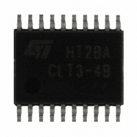
CLT3-4BT6-TR STMicroelectronics, CLT3-4BT6-TR Datasheet - Page 4

CLT3-4BT6-TR
Manufacturer Part Number
CLT3-4BT6-TR
Description
TERMINATION QUAD DGTL TSSOP-20
Manufacturer
STMicroelectronics
Type
Digital Terminationr
Datasheet
1.CLT3-4BT6-TR.pdf
(13 pages)
Specifications of CLT3-4BT6-TR
Technology
Mixed Technology
Number Of Circuits
4
Applications
General Purpose
Package / Case
20-TSSOP
Diode Type
ESD Protection
Clamping Voltage Vc Max
38V
Operating Voltage
10V
Diode Case Style
TSSOP
No. Of Pins
20
Operating Supply Voltage
10 V
Supply Current
0.0008 A
Maximum Operating Temperature
+ 85 C
Minimum Operating Temperature
- 25 C
Mounting Style
SMD/SMT
For Use With
497-6401 - BOARD EVAL FOR CLT3-4
Lead Free Status / RoHS Status
Lead free / RoHS Compliant
Power (watts)
-
Voltage - Working
-
Voltage - Clamping
-
Lead Free Status / Rohs Status
Details
Other names
497-2455-2
Available stocks
Company
Part Number
Manufacturer
Quantity
Price
Part Number:
CLT3-4BT6-TR
Manufacturer:
ST
Quantity:
20 000
Characteristics
1.1
4/13
Table 5.
1. Refer to Application note AN2527 for test conditions.
2. See test circuit in
Figure 3.
Functional description
The CLT3-4 is a quadruple input digital termination device designed for 24 V DC automation
applications. It provides the front-end circuitry of a digital input module (I/O) in industrial
automation, and drives an isolating opto-coupler.
Available in a four channels configuration, it offers a high-density termination by minimizing
the external components count. It is housed in a TSSOP20 surface mount package to
reduce the printed board size.
Made of an input voltage protection, a serial current limiting circuit and an opto-coupler
driver, each channel circuit terminates the connection between the logic input and the
associated high side sensor or switch.
The CLT3-4 is a 3 mA quad channel device compatible the type 1 and 3 characteristics of
the IEC 61131-2 standard.
Each input voltage clamping block protects the module input against electromagnetic
interferences such as those described in the IEC 61131-2 standard and IEC 61000-4-2
(ESD), 4-4 (transient burst), 4-5 (voltage surge) standards. The supply input is also
designed with such a protection structure.
Symbol
V
V
V
V
PPB
PP
PP
PP
Node
V
IN
CLT3 System electromagnetic compatibility ratings,
R
V
V
Typical junction to ambient thermal resistance versus copper surface
under common pad (FR4 epoxy, copper thickness is 35 µm)
CC
I
I
I
= 1.8 kΩ, R
Figure
ESD protection, IEC 61000-4-2, per input, in air
ESD protection, IEC 61000-4-2, per input, in contact
ESD protection, IEC 61000-4-2, per input, in air, R
ESD protection, IEC 61000-4-2, per input, in contact, R
Total Peak Pulse Voltage Burst, IEC 61000-4-4
C
Peak Pulse Voltage Surge, IEC 61000-4-5, R = 42 Ω
Peak Pulse Voltage Surge, IEC 61000-4-5, R = 2 Ω
160
140
120
100
IN
80
60
40
20
0
0.0
= 100 pF, C
12.
R
th(j-a) (
0.5
C
° C/W)
= 4.7 kΩ (unless otherwise specified)
Parameter name and conditions
1.0
OUT
1.5
= 22 nF, F = 5 kHz
2.0
S(cm²)
2.5
3.0
3.5
(1)
4.0
4.5
I
= 0 Ω
(2)
(2)
5.0
I
= 0 Ω
Value
± 8
± 6
± 3
± 3
± 4
± 1
± 1
CLT3-4B
Unit
kV
kV
kV
kV
kV
kV
kV


