LM2941SX/NOPB National Semiconductor, LM2941SX/NOPB Datasheet - Page 3
LM2941SX/NOPB
Manufacturer Part Number
LM2941SX/NOPB
Description
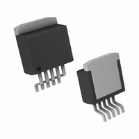
IC REGULATOR LDO 1A TO-263-5
Manufacturer
National Semiconductor
Type
Voltage Regulatorr
Specifications of LM2941SX/NOPB
Regulator Topology
Positive Adjustable
Voltage - Output
5 ~ 20 V
Voltage - Input
Up to 26V
Voltage - Dropout (typical)
0.5V @ 1A
Number Of Regulators
1
Current - Output
1A
Operating Temperature
-40°C ~ 125°C
Mounting Type
Surface Mount
Package / Case
TO-263-5, D²Pak (5 leads + Tab), TO-263BA
Current, Output
1 A
Current, Supply
10 mA
Package Type
TO-263
Regulation, Line
4 mV/V
Regulation, Load
7 mV/V
Regulator Type
Low Dropout
Resistance, Thermal, Junction To Case
3 °C/W
Temperature, Operating, Range
-40 to +125 °C
Voltage, Dropout
0.5 V
Voltage, Input
31 VDC
Voltage, Noise
0.003 %
Voltage, Output
5 to 20 V
Voltage, Supply, Rejection Ratio
0.005 %/V
Lead Free Status / RoHS Status
Lead free / RoHS Compliant
Current - Limit (min)
-
Lead Free Status / Rohs Status
RoHS Compliant part
Other names
LM2941SX
LM2941SXTR
LM2941SXTR
Available stocks
Company
Part Number
Manufacturer
Quantity
Price
Company:

Part Number:
LM2941SX/NOPB
Manufacturer:
TI
Quantity:
2 400
Part Number:
LM2941SX/NOPB
Manufacturer:
TI/德州仪器
Quantity:
20 000


Reference Voltage
Line Regulation
Load Regulation
Output Impedance
Quiescent Current
RMS Output Noise,
% of V
Ripple Rejection
Long Term Stability
Dropout Voltage
Short Circuit Current
Maximum Line
Transient
Maximum Operational Input
Voltage
Reverse Polarity DC Input Voltage R
Reverse Polarity Transient Input
Voltage
ON/OFF Threshold Voltage ON
ON/OFF Threshold Voltage OFF
ON/OFF Threshold Current
Thermal Resistance
Junction-to-Case
Thermal Resistance
Junction-to-Ambient
Electrical Characteristics—LM2941CT, LM2941CS
5V
while those in boldface type apply over the full Operating Temperature Range.
Thermal Performance
Note 1: Absolute Maximum Ratings indicate limits beyond which damage to the device may occur. Operating ratings indicate conditions for which the device is
intended to be functional, but device parameter specifications may not be guaranteed under these conditions. For guaranteed specifications and test conditions,
see the Electrical Characteristics.
Note 2: The Human Body Model (HBM) is a 100 pF capacitor discharged through a 1.5kΩ resistor into each pin. Test method is per JESD22–A114.
Note 3: A military RETS specification available upon request. For more information about military-aerospace products, see the Mil-Aero web page at http://
www.national.com/appinfo/milaero/index.html.
Note 4: The maximum power dissipation is a function of T
(T
is used, the thermal resistance can be reduced by increasing the P.C. board copper area thermally connected to the package: Using 0.5 square inches of copper
area, θ
for the LLP package was obtained using a JESD51-7 board with six vias, using no airflow and an ambient temperature of 22°C. The value θ
is specifically dependent on PCB trace area, trace material, and the number of layers and thermal vias. For improved thermal resistance and power dissipation
for the LLP package, refer to Application Note AN-1187. It is recommended that 6 vias be placed under the center pad to improve thermal performance.
Note 5: All limits guaranteed at room temperature (standard typeface) and at temperature extremes (boldface type). All limits are used to calculate Outgoing
Quality Level, and are 100% production tested.
J
(max) − T
≤
OUT
V
JA
O
is 50°C/W; with 1 square inch of copper area, θ
≤
Parameter
A
)/θ
20V, V
JA
. If this dissipation is exceeded, the die temperature will rise above 150°C and the LM2941 will go into thermal shutdown. If the TO-263 package
IN
= V
O
+ 5V, C
5-Lead TO-220
5-Lead TO-263
5-Lead TO-220
5-Lead TO-263
8-Lead LLP (Note 4)
5mA
V
50mA
100 mADC and 20 mArms
f
V
V
10Hz–100kHz
I
f
I
I
V
V
R
T
I
I
V
O
O
O
O
O
O
O
O
O
O
IN
IN
O
ON/OFF
O
O
≤
= 22μF, unless otherwise specified. Specifications in standard typeface apply for T
= 120Hz
= 5mA
= 120Hz, 1 Vrms, I
= 1A
= 100mA
≤
≤
+ 2V
+ 2V
Max 1V Above Nominal V
= 100Ω, T
= 100Ω, V
= V
Max = 26V (Note 8)
100ms, R
1A
1A
≤
≤
O
I
O
= 2.0V, I
≤
I
≤
+ 5V, I
O
≤
V
V
≤
1A (Note 7)
IN
IN
JA
1A
O
O
J
≤
(max), θ
≤
< 26V, I
is 37°C/W; and with 1.6 or more square inches of copper area, θ
≥
O
= 100Ω
Conditions
100ms
O
26V, I
= 1A
−0.6V
≤
1A
L
JA
O
O
= 100mA
, and T
= 5mA
= 5mA
A
O
. The maximum allowable power dissipation at any ambient temperature is P
3
53
73
35
3
3
1.275
0.003
0.005
1.30
1.30
Typ
−30
−55
110
0.4
0.5
1.9
10
30
55
31
50
4
7
7
1.237/1.211
1.313/1.339
(Note 6)
200/200
0.8/1.0
Limit
45/60
JA
0.02
0.80
2.00
−15
−45
100
1.6
10
10
15
45
26
is 32°C/W. Thermal performance
JA
for the LLP package
°C/W
°C/W
°C/W
°C/W
°C/W
mV/V(max)
mV/V(max)
www.national.com
%/1000 Hr
%/V(max)
mA(max)
mA(max)
mV(max)
J
μA(max)
(Limits)
V(max)
V(max)
V(max)
V(min)
A(min)
V(min)
V(min)
V(min)
V(min)
= 25°C,
Units
mΩ/V
V
%
DC
D
=
Related parts for LM2941SX/NOPB
Image
Part Number
Description
Manufacturer
Datasheet
Request
R

Part Number:
Description:
IC,VOLT REGULATOR,ADJUSTABLE,+1.275V TO +25V,BIPOLAR,SIP,5PIN,PLASTIC
Manufacturer:
National Semiconductor
Datasheet:

Part Number:
Description:
IC REGULATOR LDO 1A TO-263-5
Manufacturer:
National Semiconductor
Datasheet:

Part Number:
Description:
IC, ADJ LDO REG, 5V TO 20V, 1A, TO-263-5
Manufacturer:
National Semiconductor
Datasheet:
Part Number:
Description:
National Semiconductor [8-Bit D/A Converter]
Manufacturer:
National Semiconductor
Datasheet:
Part Number:
Description:
National Semiconductor [Media Coprocessor]
Manufacturer:
National Semiconductor
Datasheet:
Part Number:
Description:
Digitally Controlled Tone and Volume Circuit with Stereo Audio Power Amplifier, Microphone Preamp Stage and National 3D Sound
Manufacturer:
National Semiconductor
Datasheet:
Part Number:
Description:
Digitally Controlled Tone and Volume Circuit with Stereo Audio Power Amplifier, Microphone Preamp Stage and National 3D Sound
Manufacturer:
National Semiconductor
Datasheet:
Part Number:
Description:
AC97 Rev 2 Codec with Sample Rate Conversion and National 3D Sound
Manufacturer:
National Semiconductor
Part Number:
Description:
Manufacturer:
National Semiconductor
Datasheet:
Part Number:
Description:
Manufacturer:
National Semiconductor
Datasheet:
Part Number:
Description:
General Purpose, Low Voltage, Low Power, Rail-to-Rail Output Operational Amplifiers
Manufacturer:
National Semiconductor
Datasheet:
Part Number:
Description:
8-bit 20 MSPS flash A/D converter.
Manufacturer:
National Semiconductor
Datasheet:
Part Number:
Description:
Low Noise Quad Operational Amplifier
Manufacturer:
National Semiconductor
Datasheet: