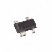
MAX6443US29L+T Maxim Integrated Products, MAX6443US29L+T Datasheet - Page 5

MAX6443US29L+T
Manufacturer Part Number
MAX6443US29L+T
Description
IC MPU RESET 2.925V SOT143-4
Manufacturer
Maxim Integrated Products
Type
Simple Reset/Power-On Resetr
Datasheet
1.MAX6443US29LT.pdf
(13 pages)
Specifications of MAX6443US29L+T
Number Of Voltages Monitored
1
Output
Push-Pull, Totem Pole
Reset
Active Low
Reset Timeout
140 ms Minimum
Voltage - Threshold
2.925V
Operating Temperature
-40°C ~ 85°C
Mounting Type
Surface Mount
Package / Case
SOT-143, SC-70-4, SC-82AB, SOT-323-4, SOT-343, SC-70-6, SC-88, SOT-363, TSLP-7
Lead Free Status / RoHS Status
Lead free / RoHS Compliant
Other names
MAX6443US29L+T
MAX6443US29L+TTR
MAX6443US29L+TTR
The reset output is typically connected to the reset
input of a microprocessor (µP). A µP’s reset input starts
or restarts the µP in a known state. The MAX6443–
MAX6452 µP supervisory circuits provide the reset
logic to prevent code-execution errors during power-
up, power-down and brownout conditions (see the
Typical Operating Circuit ).
RESET changes from high to low whenever the moni-
tored voltages (RSTIN or V
MAX6443
MAX6444
—
—
—
—
1
2
3
4
MAX6445
MAX6446
µP Reset Circuits with Long Manual Reset
—
—
—
2
1
3
4
5
_______________________________________________________________________________________
Detailed Description
MAX6447
MAX6448
PIN
—
—
—
2
1
3
4
5
CC
) drop below the reset
MAX6449
MAX6450
—
—
Reset Output
2
1
3
4
6
5
MAX6451
MAX6452
—
—
2
1
3
4
6
5
RESET
NAME
RSTIN
GND
MR1
MR2
MR2
V
CC
threshold voltages. Once V
respective reset threshold voltages, RESET remains low
for the reset timeout period and then goes high. RESET
is one-shot pulsed whenever selected manual reset
inputs are asserted. RESET stays asserted for the nor-
mal reset timeout period (140ms min).
RESET is guaranteed to be in the proper output logic
state for V
reset logic when V
Valid RESET Output Down to V
Ground
Acti ve- Low P ush- P ul l or Op en- D r ai n Outp ut. RE S E T
chang es fr om hi g h to l ow w hen V
i ts sel ected r eset thr eshol d and r em ai ns l ow for the 210m s
r eset ti m eout p er i od after al l m oni tor ed p ow er - sup p l y i np uts
exceed thei r sel ected r eset thr eshol d s. RE S E T i s one- shot
p ul sed l ow for the r eset ti m eout p er i od ( 140m s m i n) after
sel ected m anual r eset i np uts ar e asser ted l ong er than the
sp eci fi ed setup p er i od . For the op en- d r ai n outp ut, use a
m i ni m um 20kΩ p ul l up r esi stor to V
Manual Reset Input, Active Low. Internal 50kΩ pullup to
V
to one-shot pulse RESET for the reset timeout period.
Manual Reset Input, Active Low. Pull both MR1 and
MR2 low for the typical input pulse width (t
shot pulse RESET for the reset timeout period.
V
primary microprocessor voltage reset monitor.
Manual Reset Input, Active Low. Internal 50kΩ pullup to
V
pulse width (t
timeout period.
Manual Reset Input. Pull the MR2 high to immediately
one-shot pulse RESET for the reset timeout period.
Reset Input. High-impedance input to the adjustable
reset comparator. Connect RSTIN to the center point of
an external resistor-divider to set the threshold of the
externally monitored voltage.
CC.
CC
CC
. Pull both MR1 and MR2 low for the typical input
CC
Voltage Input. Power supply and input for the
Pull MR1 low for the typical input pulse width (t
inputs ≥ 1V. For applications requiring valid
MR
CC
) to one-shot pulse RESET for the reset
is less than 1V, see the Ensuring a
Setup Period
FUNCTION
RSTIN
CC
Pin Description
C C
= 0V section.
C C
and V
or RS TIN d r op s b el ow
.
CC
MR
exceed their
) to one-
MR
)
5


