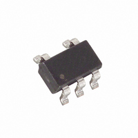
MAX6414UK29+T Maxim Integrated Products, MAX6414UK29+T Datasheet - Page 6

MAX6414UK29+T
Manufacturer Part Number
MAX6414UK29+T
Description
IC MPU/RESET CIRC 2.925V SOT23-5
Manufacturer
Maxim Integrated Products
Type
Simple Reset/Power-On Resetr
Datasheet
1.MAX6417UKT.pdf
(12 pages)
Specifications of MAX6414UK29+T
Number Of Voltages Monitored
1
Output
Open Drain or Open Collector
Reset
Active Low
Reset Timeout
Adjustable/Selectable
Voltage - Threshold
2.925V
Operating Temperature
-40°C ~ 125°C
Mounting Type
Surface Mount
Package / Case
SOT-23-5, SC-74A, SOT-25
Monitored Voltage
1.6 V to 5 V
Undervoltage Threshold
2.852 V
Overvoltage Threshold
2.998 V
Manual Reset
Resettable
Watchdog
No
Battery Backup Switching
No
Power-up Reset Delay (typ)
5.4 ms
Supply Voltage (max)
5.5 V
Supply Voltage (min)
1 V
Supply Current (typ)
2.7 uA (Typ)
Maximum Power Dissipation
571 mW
Mounting Style
SMD/SMT
Maximum Operating Temperature
+ 125 C
Chip Enable Signals
No
Minimum Operating Temperature
- 40 C
Output Type
Active Low or Open Drain
Power Fail Detection
No
Lead Free Status / RoHS Status
Lead free / RoHS Compliant
Other names
MAX6414UK29+TTR
The MAX6415–MAX6420 monitor the voltage on RESET
IN with an external resistor voltage-divider (Figure 1).
Use the following formula to calculate the externally
monitored voltage (V
where V
and V
R1 and R2 can have very high values to minimize cur-
rent consumption due to low leakage currents. Set R2
to some conveniently high value (1MΩ, for example)
and calculate R1 based on the desired monitored volt-
age, using the following formula:
Many µP-based products require manual reset capabil-
ity, allowing the operator, a technician, or external logic
circuitry to initiate a reset. A logic low on MR asserts
reset. Reset remains asserted while MR is low and for
the reset timeout period after MR returns high.
The MR has an internal 20kΩ pullup resistor so it can
be left open if not used. Connect a normally open
momentary switch from MR to ground to create a man-
ual reset function (external debounce circuitry is not
required for long reset timeout periods).
A manual reset option can easily be implemented with the
MAX6415–MAX6420 by connecting a normally open
momentary switch in parallel with R2 (Figure 2). When the
switch is closed, the voltage on RESET IN goes to zero,
Low-Power, Single/Dual-Voltage µP Reset Circuits
with Capacitor-Adjustable Reset Timeout Delay
Figure 1. Calculating the Monitored Threshold Voltage (V
6
_______________________________________________________________________________________
RST
R1
R2
V
MON_TH
MON_TH
is the reset input threshold (1.26V). Resistors
R1 = R2 x (V
V
MON_TH
SRT
RESET IN
GND
(MAX6412/MAX6413/MAX6414)
is the desired reset threshold voltage
MAX6415
MAX6416
MAX6417
MON_TH
= V
MON_TH
RST
V
):
CC
Manual Reset Input
(R1 + R2)/R2
/V
V
RST
MON_TH
Reset Threshold
- 1) (Ω)
= 1.26 x (R1 + R2)/R2
MON_TH
)
initiating a reset. Similar to the MAX6412/MAX6413/
MAX6414 manual reset, reset remains asserted while the
switch is closed and for the reset timeout period after the
switch is opened.
The MAX6415/MAX6416/MAX6417 contain an adjustable
reset threshold input. These devices can be used to
monitor voltages other than V
shown in the Reset Threshold section. (See Figure 3.)
Figure 2. Adding an External Manual Reset Function to the
MAX6415–MAX6420
Figure 3. Monitoring External Voltages
Monitoring Voltages Other than V
R1
R2
V
MON_TH
R1
R2
(MAX6415/MAX6416/MAX6417)
V
CC
RESET IN
GND
SRT
SRT
RESET IN
GND
MAX6415
MAX6416
MAX6417
MAX6415–
MAX6420
CC
. Calculate V
V
CC
V
CC
V
CC
MON_TH
CC
as


