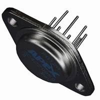
PA12A Cirrus Logic Inc, PA12A Datasheet - Page 4

PA12A
Manufacturer Part Number
PA12A
Description
IC PWR AMP 90V 10A A GRADE 8P TO
Manufacturer
Cirrus Logic Inc
Series
Apex Precision Power™r
Specifications of PA12A
Amplifier Type
Power
Number Of Circuits
1
Slew Rate
4 V/µs
Gain Bandwidth Product
4MHz
Current - Input Bias
10nA
Voltage - Input Offset
1000µV
Current - Supply
25mA
Current - Output / Channel
15A
Voltage - Supply, Single/dual (±)
20 V ~ 100 V, ±10 V ~ 50 V
Operating Temperature
-55°C ~ 125°C
Mounting Type
Through Hole
Package / Case
TO-3-8
Number Of Channels
1
Voltage Gain Db
110 dB
Common Mode Rejection Ratio (min)
74 dB
Input Offset Voltage
4 mV
Maximum Operating Temperature
+ 125 C
Mounting Style
Through Hole
Maximum Dual Supply Voltage
+/- 45 V
Minimum Operating Temperature
- 55 C
Lead Free Status / RoHS Status
Contains lead / RoHS compliant by exemption
Output Type
-
-3db Bandwidth
-
Lead Free Status / Rohs Status
Details
Other names
598-1304
Available stocks
Company
Part Number
Manufacturer
Quantity
Price
Part Number:
PA12A
Manufacturer:
APEX
Quantity:
20 000
PA12 • PA12A
GENERAL
siderations" which covers stability, supplies, heat sinking,
mounting, current limit, SOA interpretation, and specification
interpretation. Visit www.Cirrus.com for design tools that help
automate tasks such as calculations for stability, internal power
dissipation, current limit; heat sink selection; Apex Precision
Power’s complete Application Notes library; Technical Seminar
Workbook; and Evaluation Kits.
SAFE OPERATING AREA (SOA)
limitations:
1. The current handling capability of the transistor geometry
2. The second breakdown effect which occurs whenever the
3. The junction temperature of the output transistors.
Op Amp. For a given application, the direction and magnitude
of the output current should be calculated or measured and
checked against the SOA curves. This is simple for resistive
loads but more complex for reactive and EMF generating
loads. However, the following guidelines may save extensive
analytical efforts.
1. Capacitive and dynamic* inductive loads up to the following
*If the inductive load is driven near steady state conditions,
allowing the output voltage to drop more than 8V below the
supply rail with I
= 5A while the amplifier is current limiting, the inductor must
be capacitively coupled or the current limit must be lowered
to meet SOA criteria.
2. The amplifier can handle any EMF generating or reactive
4
50V
40V
35V
30V
25V
20V
15V
±V
Please read Application Note 1 "General Operating Con-
The output stage of most power amplifiers has three distinct
The SOA curves combine the effect of all limits for this Power
and the wire bonds.
simultaneous collector current and collector-emitter voltage
exceeds specified limits.
maximum are safe with the current limits set as specified.
S
6.0
4.0
3.0
2.0
1.0
SUPPLY TO OUTPUT DIFFERENTIAL VOLTAGE, V
15
10
.6
.4
.3
10
I
LIM
150mF
200µF
500µF
2.0mF
CAPACITIVE LOAD
7.0mF
25mF
60mF
LIM
= 5A
= 15A or 25V below the supply rail with I
20
SECOND BREAKDOWN
I
LIM
125µF
350µF
850µF
2.5mF
20mF
60mF
10mF
30
= 10A
SOA
40
1,000mH
2,500mH
I
50
150mH
500mH
LIM
15mH
50mH
INDUCTIVE LOAD
5mH
= 5A
70
S
- V
I
100
LIM
2.0mH
3.0mH
5.0mH
O
10mH
20mH
30mH
50mH
(V)
= 10A
LIM
P r o d u c t I n n o v a t i o n F r o m
These simplified limits may be exceeded with further analysis
using the operating conditions for a specific application.
CURRENT LIMITING
both fixed and foldover current limit operation. Visit the Apex
Precision Power web site at www.Cirrus.com for a copy of the
Power Design spreadsheet (Excel) which plots current limits vs.
steady state SOA. Beware that current limit should be thought
of as a +/–20% function initially and varies about 2:1 over the
range of –55°C to 125°C.
1 and 2.
to the current limit which allows more power to be delivered
to the load without violating the SOA. For maximum foldover
slope, ground pin 7 and use equations 3 and 4.
desired current at 0v out, or with equation 4 to set R
maximum output voltage. Equation 3 should then be used to
plot the resulting foldover limits on the SOA graph. If equa-
tion 3 results in a negative current limit, foldover slope must
be reduced. This can happen when the output voltage is the
opposite polarity of the supply conducting the current.
this can be achieved by adding a resistor (R
7 and ground. Use equations 4 and 5 with this new resistor
in the circuit.
Where:
R
FO
Refer to Application Note 9, "Current Limiting", for details of
For fixed current limit, leave pin 7 open and use equations
R
I
Where:
I
R
For certain applications, foldover current limit adds a slope
Where:
Vo is the output voltage in volts.
Most designers start with either equation 1 to set R
In applications where a reduced foldover slope is desired,
load and short circuits to the supply rail or common if the
current limits are set as follows at T
CL
CL
CL
CL
is in K ohms.
= 0.65/R
is the current limit in amperes.
50V
40V
35V
30V
25V
20V
15V
±V
= 0.65/L
is the current limit resistor in ohms.
S
CL
R
CL
I
CL
CL
R
I
=
CL
=
CL
C, L, OR EMF LOAD
=
0.65 + (Vo * 0.014)
0.65 + (Vo * 0.014)
=
SHORT TO ±V
0.65 +
0.65 +
.30A
.58A
.87A
2.4A
2.9A
4.2A
1.5A
R
I
R
I
CL
CL
CL
CL
10.14 + R
10.14 + R
Vo * 0.14
Vo * 0.14
S
C
= 25°C:
FO
FO
FO
) between pin
SHORT TO
COMMON
2.4A
2.9A
3.7A
4.1A
4.9A
6.3A
8.0A
CL
CL
PA12U
for the
(1)
(2)
(3)
(4)
at the
(5)
(6)


