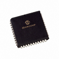
PIC18F452-I/LG Microchip Technology, PIC18F452-I/LG Datasheet - Page 2

PIC18F452-I/LG
Manufacturer Part Number
PIC18F452-I/LG
Description
IC MCU FLASH 16KX16 W/AD 44PLCC
Manufacturer
Microchip Technology
Series
PIC® 18Fr
Datasheets
1.PIC16F616T-ISL.pdf
(8 pages)
2.PIC18F242-ISO.pdf
(332 pages)
3.PIC18F242-ISO.pdf
(14 pages)
4.PIC18F242-ISO.pdf
(16 pages)
5.PIC18F242-ISO.pdf
(16 pages)
6.PIC18F242-ISO.pdf
(14 pages)
7.PIC18LF242-ISO.pdf
(36 pages)
Specifications of PIC18F452-I/LG
Core Processor
PIC
Core Size
8-Bit
Speed
40MHz
Connectivity
I²C, SPI, UART/USART
Peripherals
Brown-out Detect/Reset, LVD, POR, PWM, WDT
Number Of I /o
34
Program Memory Size
32KB (16K x 16)
Program Memory Type
FLASH
Eeprom Size
256 x 8
Ram Size
1.5K x 8
Voltage - Supply (vcc/vdd)
4.2 V ~ 5.5 V
Data Converters
A/D 8x10b
Oscillator Type
External
Operating Temperature
-40°C ~ 85°C
Package / Case
44-PLCC
For Use With
XLT44L2 - SOCKET TRAN ICE 44PLCCDVA16XL441 - ADAPTER DEVICE ICE 44PLCC
Lead Free Status / RoHS Status
Lead free / RoHS Compliant
PIC18FXX2
3. Module: Interrupts
DS80150D-page 2
Note:
Under certain conditions, the use of dual priority
interrupts may cause a program instruction to be
skipped entirely. This has only been observed
when both of the following apply:
• Both high and low interrupts are enabled, and
• A high priority asynchronous interrupt occurs in
The event causes the stack to get pushed twice,
and will eventually result in an overflow.
Work around
Two possible solutions are presented. Other
solutions may exist.
1. Enable only high priority interrupts for all
2. If it is necessary to use both high and low
Date Codes that pertain to this issue:
All engineering and production devices.
the following cycle after any low priority
interrupt.
sources, both synchronous and asynchronous.
interrupt priorities:
• Assign asynchronous interrupts as low
• Assign synchronous interrupts to both high
priority only.
and low priority, as needed.
This does not apply to the INT0 (external)
interrupt, as it is always configured as a
high priority interrupt.
4. Module: Core (Program Memory Space)
5. Module: Data EEPROM
Performing table read operations above the user
program
1FFFFFh) may yield erroneous results at the
extreme low end of the device’s rated temperature
range (-40°C).
This applies specifically to addresses above
1FFFFFh,
(200000h-200007h),
(300000h-30000Dh), and the device ID locations
(3FFFFEh and 3FFFFFh). User program memory
is unaffected.
Work around
Three possible work arounds are presented. Other
solutions may exist.
1. Do not perform table read operations on areas
2. Insert NOP instructions (specifically, literal
Date Codes that pertain to this issue:
All engineering and production devices.
When reading the data EEPROM, the contents of
the EEDATA register may be corrupted if the RD
bit (EECON1<0>) is set immediately following a
write to the address byte (EEADR). The actual
contents of the data EEPROM remain unaffected.
Work around
Do not set EEADR immediately before the
execution of a read. Write to EEADR at least one
instruction cycle before setting the RD bit. The
instruction between the write to EEADR and the
read can be any valid instruction, including a NOP.
Date Codes that pertain to this issue:
All engineering and production devices.
above the user memory space at -40°C.
FFFFh) around any table read instructions.
The suggested optimal number is 4 instruc-
tions before and 8 instructions after each table
read. This may vary depending upon the
particular application, and should be optimized
by the user.
memory
including
© 2005 Microchip Technology Inc.
space
the
the
configuration
user
(addresses
ID
locations
bytes
over


