PIC16C745/JW Microchip Technology, PIC16C745/JW Datasheet
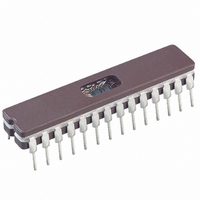
IC MCU EPROM8KX14 USB A/D 28CDIP

PIC16C745/JW

Manufacturer Part Number
PIC16C745/JW
Description
IC MCU EPROM8KX14 USB A/D 28CDIP
Manufacturer
Microchip Technology
Series
PIC® 16Cr

Specifications of PIC16C745/JW

Core Processor
PIC
Core Size
8-Bit
Speed
24MHz
Connectivity
SCI, UART/USART, USB
Peripherals
Brown-out Detect/Reset, POR, PWM, WDT
Number Of I /o
22
Program Memory Size
14KB (8K x 14)
Program Memory Type
EPROM, UV
Ram Size
256 x 8
Voltage - Supply (vcc/vdd)
4.35 V ~ 5.25 V
Data Converters
A/D 5x8b
Oscillator Type
External
Operating Temperature
0°C ~ 70°C
Package / Case
28-CDIP (0.300", 7.62mm) Window
Lead Free Status / RoHS Status
Contains lead / RoHS non-compliant
Eeprom Size
-

Available stocks

Company
Part Number
Manufacturer
Quantity
Price
Part Number:
PIC16C745/JW
Manufacturer:
MICROCHIP
Quantity:
51
Part Number:
PIC16C745/JW
Manufacturer:
MICROCHIP
Quantity:
1 000
Part Number:
PIC16C745/JW
Manufacturer:
MICROCHIP/微芯
Quantity:
20 000
The PIC16C745/765 (Rev. A1) parts you have received
conform functionally to the PIC16C745/765 Data Sheet
(DS41124C), except for the anomalies described
below.
All significant issues listed here are addressed by Rev.
A2 of the PIC16C745/765 silicon.
1.
The first bit in the sync pattern during Microcontroller-
to-host transactions is elongated by approximately
100 ns (see Figure 1). According to Section 7.1.11 of
the USB Specification, Version 1.1, the bit period for a
low speed device can vary 1.5% from 667 ns. This
FIGURE 1: USB TRANSCEIVER TIMING
2002 Microchip Technology Inc.
Note:
Module: USB Transceiver
PIC16C745/765 Rev. A1 Silicon/Data Sheet Errata
The silicon revision of a specific compo-
nent is identified by its manufacture date
code: YYWW. YY is the year of manufac-
ture and WW is the specific work week. All
material with a date code of 0230 or earlier
is Rev. A1 silicon and subject to this Errata
document. Components with a date code
later than 0230 will be Rev. A2 silicon and
will be covered by a separate Errata docu-
ment. For additional information concern-
ing date codes, refer to the packaging
information section of the PIC16C745/765
Data Sheet (DS41124C)
D -
D +
SOP
772 ns
First Bit
of Packet
667 ns
PIC16C745/765
667 ns
means the average bit length can vary from 657 ns to
676 ns. Section 7.1.13.1 states, “For low speed trans-
missions, the jitter time for any consecutive differential
data transitions must be within
transitions.”
The initial bit from the PIC16C745/765, at approxi-
mately 772 ns in length, violates the consecutive transi-
tion jitter specification by 71 ns to 90 ns, depending on
the actual data rate. It violates the paired data transition
jitter specification by 82 ns to 120 ns, depending on the
actual data rate. Devices based on the PIC16C745/765
are likely to fail the USB Implementer’s Forum Compli-
ance Test due to the jitter violation. However, the elon-
gated bit does not affect the reliability of USB
transactions between current USB host controllers and
the PIC16C745/765. All packets are communicated
successfully between microcontroller and host.
Work Around
No work around available.
10 ns for any set of paired differential data
Note:
USB-IF certification is necessary only if
use of the USB logo is desired.
. . .
25 ns and within
DS80114C-page 1

Related parts for PIC16C745/JW

PIC16C745/JW Summary of contents

Page 1

... FIGURE 1: USB TRANSCEIVER TIMING 772 SOP 2002 Microchip Technology Inc. PIC16C745/765 means the average bit length can vary from 657 ns to 676 ns. Section 7.1.13.1 states, “For low speed trans- missions, the jitter time for any consecutive differential data transitions must be within 10 ns for any set of paired differential data transitions.” ...

Page 2

... Figure 2). If additional transactions arrive prior to clearing the TOK_DNE bit, they will be lost. FIGURE 2: UIR / USTAT REGISTER UIR DS80114C-page 2 Work around The interrupt driver Microchip firmware does not lose any transactions with current operating systems. QUEUE not empty TOK_DNE bit USTAT FIFO 2002 Microchip Technology Inc. ...

Page 3

... INT FIGURE 7-1: TIMER1 BLOCK DIAGRAM Set flag bit TMR1IF on Overflow TMR1 TMR1H T1OSC RC0/T1OSO/T1CKI RC1/T1OSI/CCP2 Note 1: When the T1OSCEN bit is cleared, the inverter is turned off. This eliminates power drain. 2002 Microchip Technology Inc. /4. TMR1L TMR1ON on/off T1SYNC 1 Prescaler T1OSCEN Enable F ...

Page 4

... USB Transceiver Timing was added to page 1. Rev B Document (6/02) Under the Clarifications/Corrections to the Data Sheet, Issue 1 (Timer1) was added (page 2). Rev C Document (9/02) All reference to PIC16C745 in this Errata document is changed to PIC16C745/765. All reference to Rev this Errata document is changed to Rev. A1. DS80114C-page 4 2002 Microchip Technology Inc. ...

Page 5

... Serialized Quick Turn Programming (SQTP service mark of Microchip Technology Incorporated in the U.S.A. All other trademarks mentioned herein are property of their respective companies. © 2002, Microchip Technology Incorporated, Printed in the U.S.A., All Rights Reserved. Printed on recycled paper. Microchip received QS-9000 quality system ...

Page 6

... Korea Microchip Technology Korea 168-1, Youngbo Bldg. 3 Floor Samsung-Dong, Kangnam-Ku Seoul, Korea 135-882 Tel: 82-2-554-7200 Fax: 82-2-558-5934 Singapore Microchip Technology Singapore Pte Ltd. 200 Middle Road #07-02 Prime Centre Singapore, 188980 Tel: 65-6334-8870 Fax: 65-6334-8850 Taiwan Microchip Technology (Barbados) Inc., Taiwan Branch 11F-3, No ...

Related keywords