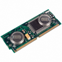
DS2252T-128-16 Maxim Integrated Products, DS2252T-128-16 Datasheet - Page 5

DS2252T-128-16
Manufacturer Part Number
DS2252T-128-16
Description
IC MICROCNTRLR 128K 16MHZ 40SIMM
Manufacturer
Maxim Integrated Products
Series
DS225xr
Datasheet
1.DS2252T-64-16.pdf
(16 pages)
Specifications of DS2252T-128-16
Core Processor
8051
Core Size
8-Bit
Speed
16MHz
Connectivity
SIO, UART/USART
Peripherals
Power-Fail Reset, WDT
Number Of I /o
32
Program Memory Type
SRAM
Ram Size
128K x 8
Voltage - Supply (vcc/vdd)
4.5 V ~ 5.5 V
Oscillator Type
External
Operating Temperature
0°C ~ 70°C
Package / Case
40-SIMM
Processor Series
DS2252T
Core
8051
Data Bus Width
8 bit
Program Memory Size
128 KB
Data Ram Size
128 KB
Interface Type
UART
Maximum Clock Frequency
16 MHz
Number Of Programmable I/os
32
Number Of Timers
2
Operating Supply Voltage
4.75 V to 5.25 V
Maximum Operating Temperature
+ 70 C
Mounting Style
SMD/SMT
Minimum Operating Temperature
0 C
Lead Free Status / RoHS Status
Contains lead / RoHS non-compliant
Eeprom Size
-
Program Memory Size
-
Data Converters
-
Lead Free Status / Rohs Status
No
Other names
DS2252T12816
Available stocks
Company
Part Number
Manufacturer
Quantity
Price
Company:
Part Number:
DS2252T-128-16#
Manufacturer:
SILICON
Quantity:
101
INSTRUCTION SET
The DS2252T executes an instruction set that is object code-compatible with the industry standard 8051
microcontroller. As a result, software development packages such as assemblers and compilers that have
been written for the 8051 are compatible with the DS2252T. A complete description of the instruction set
and operation are provided in the Secure Microcontroller User’s Guide.
MEMORY ORGANIZATION
Figure 2 illustrates the memory map accessed by the DS2252T. The entire 64k of program and 64k of
data are available to the Byte-wide bus. This preserves the I/O ports for application use. An alternate
configuration allows dynamic Partitioning of a 64k space as shown in Figure 3. Any data area not mapped
into the NV RAM is reached via the Expanded bus on Ports 0 and 2. Off-board program memory is not
available for security reasons. Selecting PES = 1 provides access to the real-time clock as shown in
Figure 4. These selections are made using Special Function Registers. The memory map and its controls
are covered in detail in the Secure Microcontroller User’s Guide.
35, 37
PIN
17
22
39
24
20
2
RST - Active high reset input. A logic 1 applied to this pin will activate a reset state.
This pin is pulled down internally, can be left unconnected if not used. An RC power-
on reset circuit is not needed and is NOT recommended.
ALE - Address Latch Enable. Used to de-multiplex the multiplexed Expanded
Address/Data bus on Port 0. This pin is normally connected to the clock input on a
’373 type transparent latch.
XTAL2, XTAL1. Used to connect an external crystal to the internal oscillator. XTAL1
is the input to an inverting amplifier and XTAL2 is the output.
GND - Logic ground.
V
debounced so that only one edge is detected. If connected to ground, the
microcontroller will enter Bootstrap loading on power up. This signal is pulled up
internally.
SDI – Self-Destruct Input. A logic 1 applied to this input causes a hardware unlock.
This involves the destruction of Encryption Keys, Vector RAM, and the momentary
removal of power from V
PROG
CC
- +5V.
- Invokes the Bootstrap loader on a falling edge. This signal should be
CCO
. This pin should be grounded if not used.
5 of 16
DESCRIPTION


