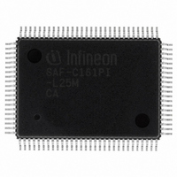
SAF-C161PI-L25M CA Infineon Technologies, SAF-C161PI-L25M CA Datasheet - Page 54

SAF-C161PI-L25M CA
Manufacturer Part Number
SAF-C161PI-L25M CA
Description
IC MCU 16BIT ROM/LESS MQFP-100-2
Manufacturer
Infineon Technologies
Series
C16xxr
Datasheet
1.SAF-C161PI-LM_CA.pdf
(82 pages)
Specifications of SAF-C161PI-L25M CA
Core Processor
C166
Core Size
16-Bit
Speed
25MHz
Connectivity
EBI/EMI, I²C, SPI, UART/USART
Peripherals
POR, PWM, WDT
Number Of I /o
76
Program Memory Type
ROMless
Ram Size
3K x 8
Voltage - Supply (vcc/vdd)
4.5 V ~ 5.5 V
Data Converters
A/D 4x10b
Oscillator Type
Internal
Operating Temperature
-40°C ~ 85°C
Package / Case
100-SQFP
Data Bus Width
16 bit
Data Ram Size
3 KB
Interface Type
ASC, I2C, SSC
Maximum Clock Frequency
25 MHz
Number Of Programmable I/os
76
Number Of Timers
5
Maximum Operating Temperature
+ 85 C
Mounting Style
SMD/SMT
Minimum Operating Temperature
- 40 C
On-chip Adc
10 bit, 4 Channel
Packages
PG-MQFP-100
Max Clock Frequency
25.0 MHz
Sram (incl. Cache)
3.0 KByte
A / D Input Lines (incl. Fadc)
4
Program Memory
0.0 KByte
Lead Free Status / RoHS Status
Lead free / RoHS Compliant
Eeprom Size
-
Program Memory Size
-
Lead Free Status / Rohs Status
Details
Other names
F161PIL25MCAXT
SAF-C161PI-L25MCA
SAF-C161PI-L25MCAINTR
SAF-C161PI-L25MCATR
SAF-C161PI-L25MCATR
SAFC161PIL25MCAXT
SP000014368
SAF-C161PI-L25MCA
SAF-C161PI-L25MCAINTR
SAF-C161PI-L25MCATR
SAF-C161PI-L25MCATR
SAFC161PIL25MCAXT
SP000014368
Data Sheet
Sample time and conversion time of the C161PI’s A/D Converter are programmable. The
table below should be used to calculate the above timings.
The limit values for
Table 9
ADCON.15|14
(ADCTC)
00
01
10
11
Converter Timing Example:
Assumptions:
Basic clock
Sample time
Conversion time
Memory Cycle Variables
The timing tables below use three variables which are derived from the BUSCONx
registers and represent the special characteristics of the programmed memory cycle.
The following table describes, how these variables are to be computed.
Table 10
Description
ALE Extension
Memory Cycle Time Waitstates
Memory Tristate Time
A/D Converter Computation Table
Memory Cycle Variables
A/D Converter
Basic clock
CPU
CPU
CPU
CPU
CPU
BC
S
C
BC
/ 4
/ 2
/ 16
/ 8
must not be exceeded when selecting ADCTC.
= 25 MHz (i.e.
=
=
=
CPU
BC
S
+ 40
I
BC
* 8 = 1280 ns.
/ 4 = 6.25 MHz, i.e.
Symbol
A
C
F
BC
+ 2
CPU
52
CPU
10
ADCON.13|12
(ADSTC)
00
01
11
= 40 ns), ADCTC = ’00’, ADSTC = ’00’.
Values
TCL * <ALECTL>
2TCL * (15 - <MCTC>)
2TCL * (1 - <MTTC>)
= (1280 + 6400 + 80) ns = 7.8 s.
BC
= 160 ns.
Sample time
W
S
BC
BC
BC
BC
* 8
* 16
* 32
* 64
&3,
1999-07


