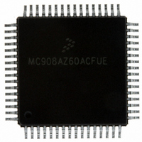
MC908AZ60ACFUE Freescale Semiconductor, MC908AZ60ACFUE Datasheet - Page 368

MC908AZ60ACFUE
Manufacturer Part Number
MC908AZ60ACFUE
Description
IC MCU FLASH 8.4MHZ 60K 64QFP
Manufacturer
Freescale Semiconductor
Series
HC08r
Datasheet
1.MC908AZ60ACFUER.pdf
(414 pages)
Specifications of MC908AZ60ACFUE
Core Processor
HC08
Core Size
8-Bit
Speed
8.4MHz
Connectivity
CAN, SCI, SPI
Peripherals
LVD, POR, PWM
Number Of I /o
52
Program Memory Size
60KB (60K x 8)
Program Memory Type
FLASH
Eeprom Size
1K x 8
Ram Size
2K x 8
Voltage - Supply (vcc/vdd)
4.5 V ~ 5.5 V
Data Converters
A/D 15x8b
Oscillator Type
Internal
Operating Temperature
-40°C ~ 85°C
Package / Case
64-QFP
Lead Free Status / RoHS Status
Lead free / RoHS Compliant
Available stocks
Company
Part Number
Manufacturer
Quantity
Price
Company:
Part Number:
MC908AZ60ACFUE
Manufacturer:
Freescale Semiconductor
Quantity:
10 000
Part Number:
MC908AZ60ACFUE
Manufacturer:
FREESCALE
Quantity:
20 000
Company:
Part Number:
MC908AZ60ACFUE1L87J
Manufacturer:
TEMIC
Quantity:
350
Company:
Part Number:
MC908AZ60ACFUER
Manufacturer:
FREESCALE
Quantity:
5 560
Company:
Part Number:
MC908AZ60ACFUER
Manufacturer:
Freescale Semiconductor
Quantity:
10 000
- Current page: 368 of 414
- Download datasheet (5Mb)
Electrical Specifications
28.1.5 Control Timing
1.
2.
3.
4.
5.
28.1.6 ADC Characteristics
1.
2.
3.
368
Resolution
Absolute Accuracy
Conversion Range
Power-Up Time
Input Leakage
Conversion Time
Monotonicity
Zero Input Reading
Full-Scale Reading
Sample Time
Input Capacitance
ADC Internal Clock
Analog Input Voltage
Bus Operating Frequency (4.5–5.5 V — V
RST Pulse Width Low
IRQ Interrupt Pulse Width Low (Edge-Triggered)
IRQ Interrupt Pulse Period
16-Bit Timer
MSCAN Wake-up Filter Pulse Width
The minimum period t
The external system error caused by input leakage current is approximately equal to the product of R source and input current.
V
The 2-bit timer prescaler is the limiting factor in determining timer resolution.
Refer to
routine plus TBD t
The minimum pulse width to wake up the MSCAN module is guaranteed by design but not tested.
V
Source impedances greater than 10 kΩ adversely affect internal RC charging time during input sampling.
(V
Input Capture Pulse Width
Input Capture Period
DD
DD
REFL
= 5.0 Vdc ± 0.5v, V
= 5.0 Vdc ± 0.5 V, V
= 0 V, V
Table 25-2. Mode, Edge, and Level Selection
(2)
(2)
(3)
DDA
(Ports B and D)
(2)
cyc
Characteristic
MC68HC908AZ60A • MC68HC908AS60A • MC68HC908AS60E Data Sheet, Rev. 6
/V
.
TLTL
DDAREF
Characteristic
SS
SS
or t
= 0 Vdc, T
(3)
= 0 Vdc, V
ILIL
= V
should not be less than the number of cycles it takes to execute the capture interrupt service
(1)
REFH
(5)
A
(1)
DDA
= –40 °C to T
= 5 V ± 0.5 V)
DD
/V
Only)
DDAREF
A
= 5.0 Vdc ± 0.5 V, V
(MAX), unless otherwise noted.
and supporting note.
V
V
500 k
Min
REFL
REFL
FE
–1
16
–1
16
00
—
8
5
Symbol
t
TH,
t
t
f
t
t
WUP
TLTL
BUS
t
ILHI
ILIL
RL
t
SSA
1.048 M
TL
V
V
Max
REFH
REFH
+1
17
17
01
FF
—
8
1
8
= 0 Vdc, V
Inherent within Total Error
Note
Note 4
Min
1.5
1.5
ADC Clock
ADC Clock
—
2
2
Cycles
Cycles
REFH
(4)
Unit
LSB
Bits
Hex
Hex
μA
pF
Hz
μs
V
V
= 5.0 Vdc ± 0.5 V
Includes Sampling Time
Freescale Semiconductor
Conversion Time Period
Max
Includes Quantization
8.4
Tested Only at 1 MHz
—
—
—
—
—
5
V
V
V
Comments
REFL
Not Tested
IN
IN
= V
= V
= V
REFH
REFL
SSA
Unit
MHz
t
t
t
t
μs
cyc
cyc
cyc
cyc
Related parts for MC908AZ60ACFUE
Image
Part Number
Description
Manufacturer
Datasheet
Request
R
Part Number:
Description:
Manufacturer:
Freescale Semiconductor, Inc
Datasheet:
Part Number:
Description:
Manufacturer:
Freescale Semiconductor, Inc
Datasheet:
Part Number:
Description:
Manufacturer:
Freescale Semiconductor, Inc
Datasheet:
Part Number:
Description:
Manufacturer:
Freescale Semiconductor, Inc
Datasheet:
Part Number:
Description:
Manufacturer:
Freescale Semiconductor, Inc
Datasheet:
Part Number:
Description:
Manufacturer:
Freescale Semiconductor, Inc
Datasheet:
Part Number:
Description:
Manufacturer:
Freescale Semiconductor, Inc
Datasheet:
Part Number:
Description:
Manufacturer:
Freescale Semiconductor, Inc
Datasheet:
Part Number:
Description:
Manufacturer:
Freescale Semiconductor, Inc
Datasheet:
Part Number:
Description:
Manufacturer:
Freescale Semiconductor, Inc
Datasheet:
Part Number:
Description:
Manufacturer:
Freescale Semiconductor, Inc
Datasheet:
Part Number:
Description:
Manufacturer:
Freescale Semiconductor, Inc
Datasheet:
Part Number:
Description:
Manufacturer:
Freescale Semiconductor, Inc
Datasheet:
Part Number:
Description:
Manufacturer:
Freescale Semiconductor, Inc
Datasheet:
Part Number:
Description:
Manufacturer:
Freescale Semiconductor, Inc
Datasheet:


