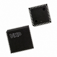
P87C591VFA/00,512 NXP Semiconductors, P87C591VFA/00,512 Datasheet - Page 38

P87C591VFA/00,512
Manufacturer Part Number
P87C591VFA/00,512
Description
IC 80C51 MCU 16K OTP 44-PLCC
Manufacturer
NXP Semiconductors
Series
87Cr
Datasheet
1.P87C591VFA00512.pdf
(160 pages)
Specifications of P87C591VFA/00,512
Core Processor
8051
Core Size
8-Bit
Speed
12MHz
Connectivity
CAN, EBI/EMI, I²C, UART/USART
Peripherals
POR, PWM, WDT
Number Of I /o
32
Program Memory Size
16KB (16K x 8)
Program Memory Type
OTP
Ram Size
512 x 8
Voltage - Supply (vcc/vdd)
4.75 V ~ 5.25 V
Data Converters
A/D 6x10b
Oscillator Type
Internal
Operating Temperature
-40°C ~ 85°C
Package / Case
44-PLCC
Processor Series
P87C5x
Core
80C51
Data Bus Width
8 bit
Data Ram Size
512 B
Interface Type
CAN, I2C, UART
Maximum Clock Frequency
12 MHz
Number Of Programmable I/os
32
Number Of Timers
3
Maximum Operating Temperature
+ 85 C
Mounting Style
SMD/SMT
3rd Party Development Tools
PK51, CA51, A51, ULINK2
Minimum Operating Temperature
- 40 C
On-chip Adc
10 bit, 6 Channel
Lead Free Status / RoHS Status
Lead free / RoHS Compliant
Eeprom Size
-
Lead Free Status / Rohs Status
Details
Other names
568-1256-5
935268182512
P87C591VFAA
935268182512
P87C591VFAA
Available stocks
Company
Part Number
Manufacturer
Quantity
Price
Company:
Part Number:
P87C591VFA/00,512
Manufacturer:
TI
Quantity:
8
Company:
Part Number:
P87C591VFA/00,512
Manufacturer:
NXP Semiconductors
Quantity:
10 000
Philips Semiconductors
12.5.5
The Interrupt Register allows the identification of an interrupt source. When one or more bits of this register are set, a
CAN interrupt will be indicated to the CPU. After this register is read by the CPU all bits are reset except of the Receive
Interrupt bit.
The Interrupt Register appears to the CPU as a read only memory.
Table 16 Interrupt Register (IR) CAN Addr. 3, bit interpretation
2000 Jul 26
IR.7
IR.6
IR.5
IR.4
IR.3
IR.2
IR.1
IR.0
BIT
Single-chip 8-bit microcontroller with CAN controller
I
NTERRUPT
SYMBOL
WUI
DOI
BEI
EPI
ALI
EI
RI
TI
R
Bus Error Interrupt
Arbitration Lost
Interrupt
Error Passive
Interrupt
Wake-Up Interrupt;
Note 1
Data Overrun
Interrupt
Error Interrupt
Transmit Interrupt;
Note 2
Receive Interrupt;
Note 2
EGISTER
NAME
(IR)
1 (set)
0 (reset)
1 (set)
0 (reset)
1 (set)
0 (reset)
1 (set)
0 (reset)
1 (set)
0 (reset)
1 (set)
0 (reset)
1 (set)
0 (reset)
1 (set)
0 (reset)
VALUE
This bit is set when the CAN controller detects an error on
the CAN Bus and the BEIE bit is set within the Interrupt
Enable Register. After a bus error interrupt event this
interrupt is locked until the Error Code Capture Register is
read out once.
This bit is set when the CAN controller has lost arbitration
and becomes a receiver and the ALIE bit is set within the
Interrupt Enable Register. After an arbitration lost interrupt
event this interrupt is locked until the Arbitration Lost Capture
Register is read out once.
This bit is set whenever the CAN controller has reached the
Error Passive Status (at least one error counter exceeds the
CAN protocol defined level of 127) or if the CAN controller is
in Error Passive Status and enters the Error Active Status
again and the EPIE bit is set within the Interrupt Enable
Register.
This bit is set when the CAN controller is sleeping and bus
activity is detected and the WUIE bit is set within the
Interrupt Enable Register.
This bit is set on a 0-to-1 change of the Data Overrun Status
bit, when the Data Overrun Interrupt Enable is set to ‘1’
(enabled).
This bit is set on every change (set and clear) of either the
Error Status or Bus Status bits if the Error Interrupt Enable is
set to ‘1’ (enabled).
This bit is set whenever the Transmit Buffer Status changes
from ‘0’ to ‘1’ (released) and Transmit Interrupt Enable is set
to ‘1’ (enabled).
This bit is set whenever the RXFIFO is filled with more bytes
than specified in the Rx Interrupt Level register or a message
has passed an acceptance filter which is set to “high priority”
and the RIE bit is set within the Interrupt Enable Register.
38
FUNCTION
Preliminary Specification
P8xC591


