IHLP5050CEERR60M01 Vishay, IHLP5050CEERR60M01 Datasheet
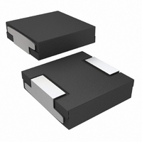
INDUCTOR POWER .60UH 29A SMD

IHLP5050CEERR60M01

Manufacturer Part Number
IHLP5050CEERR60M01
Description
INDUCTOR POWER .60UH 29A SMD
Manufacturer
Vishay
Series
IHLP®r

Specifications of IHLP5050CEERR60M01

Inductance
600nH
Current
29A
Current - Saturation
51A
Tolerance
±20%
Shielding
Shielded
Dc Resistance (dcr)
2.2 mOhm Max
Package / Case
0.520" L x 0.508" W x 0.138" H (13.20mm x 12.90mm x 3.50mm)
Mounting Type
Surface Mount
Operating Temperature
-55°C ~ 125°C
Frequency - Test
100kHz
Applications
General Purpose
Inductance Tolerance
± 20%
Dc Resistance Max
2200µohm
Dc Current Rating
29A
Core Material
Iron Powder
Inductor Case Style
5050CE
No. Of Pins
2
Svhc
No SVHC (15-Dec-2010)
Dc Current
RoHS Compliant
Lead Free Status / RoHS Status
Lead free / RoHS Compliant
Q @ Freq
-
Self Resonant Freq
-
Current - Temperature Rise
-
Lead Free Status / RoHS Status
Lead free / RoHS Compliant

Available stocks

Company
Part Number
Manufacturer
Quantity
Price
Part Number:
IHLP5050CEERR60M01
Manufacturer:
Vishay
Quantity:
500
Manufactured under one or more of the following:
US Patents; 6,198,375/6,204,744/6,449,829/6,460,244.
Several foreign patents, and other patents pending.
Notes
(1)
(2)
(3)
(4)
(5)
** Please see document “Vishay Material Category Policy”:
Document Number: 34105
Revision: 24-Feb-11
± 20 % AT 100 kHz,
IHLP-5050CE-01
GLOBAL PART NUMBER
STANDARD ELECTRICAL SPECIFICATIONS
DESCRIPTION
All test data is referenced to 25 °C ambient
Operating temperature range - 55 °C to + 125 °C
DC current (A) that will cause an approximate T of 40 °C
DC current (A) that will cause L
The part temperature (ambient + temp. rise) should not exceed
125 °C under worst case operating conditions. Circuit design,
component placement, PWB trace size and thickness, airflow
and other cooling provisions all affect the part temperature. Part
temperature should be verified in the end application.
INDUCTANCE
0.25 V, 0 A
I
MODEL
PRODUCT FAMILY
(μH)
0.10
0.15
0.22
0.33
0.47
0.60
0.68
0.82
1.0
1.5
1.8
2.2
3.3
4.7
5.6
6.8
8.2
10
L
0
H
L
INDUCTANCE VALUE
25 °C
DCR
TYP.
(m)
14.3
18.3
19.8
24.8
30.4
0.8
1.1
1.3
1.6
1.8
2.3
2.6
3.3
5.1
6.5
7.2
11
1
Low Profile, High Current IHLP
P
1.0 μH
MAX.
25 °C
DCR
(m)
0.96
1.2
1.3
1.5
2.2
2.5
3.5
5.5
12
15
19
22
28
34
2
3
7
8
0
to drop approximately 20 %
5
CURRENT
DC TYP.
RATING
HEAT
(A)
38.5
36.5
16.5
9.5
8.5
For technical questions, contact:
43
41
32
29
28
25
24
19
16
12
10
9
7
0
(3)
INDUCTANCE TOLERANCE
5
SATURATION
CURRENT
SIZE
DC TYP.
(A)
84
75
65
62
55
51
49
44
40
35
30
29
27
24
19
18
16
14
± 20 %
0
(4)
www.vishay.com/doc?99902
C
E
FEATURES
• Lowest height (3.5 mm) in this package footprint
• Shielded construction
• Frequency range up to 5.0 MHz
• Lowest DCR/μH, in this package size
• Handles high transient current spikes without
• Ultra low buzz noise, due to composite
• Compliant to RoHS Directive 2002/95/EC
APPLICATIONS
• PDA/notebook/desktop/server applications
• High current POL converters
• Low profile, high current power supplies
• Battery powered devices
• DC/DC converters in distributed power systems
• DC/DC converter for Field Programmable Gate Array (FPGA)
magnetics@vishay.com
[3.5] Max.
DIMENSIONS in inches [millimeters]
[3.5] Max.
saturation
construction
0.138
0.138
PACKAGE CODE
PACKAGE
[12.9]
[12.9]
0.508
0.508
Max.
Max.
E
CODE
[13.2 ± 0.38] Max.
0.520 ± 0.015
ER
[13.2 ± 0.38]
0.520 ± 0.015
R
[2.2 ± 0.254]
0.087 ± 0.01
®
0.091 ± 0.01
[2.3 ± 0.3]
Inductors
1
INDUCTANCE
This diagram applies to values 0.68 µH and above
VALUE
JEDEC LEAD (Pb)-FREE STANDARD
This diagram applies to values 0.6 µH and below
R
IHLP-5050CE-01
0.128 [3.3]
0
[4.95]
0.195
Typical Pad Layout
Typical Pad Layout
TOL.
e3
0.185 ± 0.01
M
0.118 ± 0.01
[4.7 ± 0.3]
[3.0 ± 0.3]
Vishay Dale
[13.76]
0.542
[13.8]
0.542
www.vishay.com
0
SERIES
0.318
0.310
[7.87]
[8.1]
1
1

Related parts for IHLP5050CEERR60M01

IHLP5050CEERR60M01 Summary of contents

Page 1

... GLOBAL PART NUMBER PRODUCT FAMILY ** Please see document “Vishay Material Category Policy”: Document Number: 34105 Revision: 24-Feb-11 FEATURES • Lowest height (3.5 mm) in this package footprint • Shielded construction • Frequency range up to 5.0 MHz • Lowest DCR/μH, in this package size • ...

Page 2

... IHLP-5050CE-01 Low Profile, High Current IHLP Vishay Dale PERFORMANCE GRAPHS IHLP-5050CE-01 0.10 µH 0.12 0.11 0.10 0.09 0.08 0.07 0.06 0. CURRENT (A) IHLP-5050CE-01 0.22 µH 0.25 0.20 0.15 0.10 0.05 0. CURRENT (A) IHLP-5050CE-01 0.47 µH 0.8 0.6 0.4 0 CURRENT (A) IHLP-5050CE-01 0.68 µH 1.0 Δ ...

Page 3

... L 6.0 40 4.0 20 2 For technical questions, contact: magnetics@vishay.com IHLP-5050CE-01 ® Inductors Vishay Dale IHLP-5050CE-01 1.5 µH ΔT ° CURRENT (A) IHLP-5050CE-01 2.2 µH ΔT ° CURRENT (A) IHLP-5050CE-01 4.7 µH ΔT ° CURRENT (A) IHLP-5050CE-01 6.8 µH ΔT °C ...

Page 4

... IHLP-5050CE-01 Low Profile, High Current IHLP Vishay Dale PERFORMANCE GRAPHS IHLP-5050CE-01 8.2 µH 12.0 10.0 8.0 6.0 4.0 2.0 0 CURRENT (A) www.vishay.com 4 16.0 100 ΔT °C 14 10.0 40 8.0 20 6 For technical questions, contact: magnetics@vishay.com ® Inductors IHLP-5050CE-01 10 µH ΔT °C ...

Page 5

... Vishay product could result in personal injury or death. Customers using or selling Vishay products not expressly indicated for use in such applications their own risk and agree to fully indemnify and hold Vishay and its distributors harmless from and against any and all claims, liabilities, expenses and damages arising or resulting in connection with such use or sale, including attorneys fees, even if such claim alleges that Vishay or its distributor was negligent regarding the design or manufacture of the part ...

Related keywords