IHLP5050FDERR47M01 Vishay, IHLP5050FDERR47M01 Datasheet

INDUCTOR POWER .47UH 41A SMD

IHLP5050FDERR47M01

Manufacturer Part Number
IHLP5050FDERR47M01
Description
INDUCTOR POWER .47UH 41A SMD
Manufacturer
Vishay
Series
IHLP®r

Specifications of IHLP5050FDERR47M01

Inductance
470nH
Package / Case
0.520" L x 0.508" W x 0.256" H (13.20mm x 12.90mm x 6.50mm)
Current
41A
Current - Saturation
63A
Tolerance
±20%
Shielding
Shielded
Dc Resistance (dcr)
1.2 mOhm Max
Mounting Type
Surface Mount
Operating Temperature
-55°C ~ 125°C
Frequency - Test
100kHz
Applications
General Purpose
Product
Inductors
Test Frequency
100 KHz
Maximum Dc Current
63 Amps
Maximum Dc Resistance
1.2 mOhms
Self Resonant Frequency
5 MHz
Dimensions
12.9 mm W x 13.2 mm L x 6.5 mm H
Operating Temperature Range
- 55 C to + 125 C
Termination Style
SMD/SMT
Dc Resistance Max
1.2mohm
Dc Current Rating
41A
Inductor Type
High Current
No. Of Pins
2
Inductance Tolerance
± 20%
Lead Free Status / RoHS Status
Lead free / RoHS Compliant
Q @ Freq
-
Self Resonant Freq
-
Current - Temperature Rise
-
Lead Free Status / Rohs Status
Lead free / RoHS Compliant
Other names
541-1031-2
IHLP5050FDERR47M01

Available stocks

Company
Part Number
Manufacturer
Quantity
Price
Part Number:
IHLP5050FDERR47M01
Manufacturer:
VISHAY
Quantity:
20 000
Part Number:
IHLP5050FDERR47M01
Manufacturer:
Vishay
Quantity:
3 500
Part Number:
IHLP5050FDERR47M01
Manufacturer:
VISHAY/威世
Quantity:
20 000
www.vishay.com
64
IHLP-5050FD-01
Vishay Dale
Manufactured under one or more of the following:
US Patents; 6,198,375/6,204,744/6,449,829/6,460,244.
Several foreign patents, and other patents pending.
NOTES:
1. All test data is referenced to 25 °C ambient
2. Operating Temperature Range - 55 °C to + 125 °C
3. DC current (A) that will cause an approximate ΔT of 40 °C
4. DC current (A) that will cause Lo to drop approximately 20 %
5. The part temperature (ambient + temp rise) should not exceed
INDUCTANCE
DESCRIPTION
STANDARD ELECTRICAL SPECIFICATIONS
GLOBAL PART NUMBER
125 °C under worst case operating conditions. Circuit design,
component placement, PWB trace size and thickness, airflow
and other cooling provisions all affect the part temperature. Part
temperature should be verified in the end application.
at 100 kHz,
0.25 V, 0 A
µH ± 20 %
I
IHLP-5050FD-01
0.10
0.15
0.22
0.30
0.33
0.40
0.47
0.56
0.68
0.82
1.0
1.2
1.5
1.8
2.2
3.3
4.7
5.6
6.8
8.2
Lo
10
MODEL
H
MODE L
TYPICAL
DCR mΩ
L
25 °C
0.47
0.53
0.63
0.70
0.83
0.90
13.1
14.5
15.8
1.0
1.2
1.4
1.6
1.7
2.1
2.5
2.8
3.5
5.7
9.3
9.3
P
DCR mΩ
25 °C
MAX
0.50
0.60
0.70
0.80
0.90
11.2
15.5
16.8
1.0
1.2
1.4
1.6
1.9
2.0
2.5
3.0
3.2
4.2
6.8
10
14
5
Low Profile, High Current Inductor
INDUCTANCE
VALUE
1.0 µH
DC AMPS
CURRENT
TYPICAL
RATING
HEAT
0
13.5
13.5
11.5
10.5
For technical questions, contact: magnetics@vishay.com
60
55
53
48
46
44
41
37
35
33
32
30
27
24
22
18
10
3
5
SIZE
SATURATION
DC AMPS
CURRENT
TYPICAL
26.5
16.5
15.5
0
120
118
112
72
65
64
63
62
60
50
49
48
45
41
40
35
30
16
INDUCTANCE
TOLERANCE
4
F
±
20 %
D
FEATURES
• Shielded construction
• Frequency range up to 5.0 MHz
• Lowest DCR/µH, in this package size
• Handles high transient current spikes without
• Ultra low buzz noise, due to composite construction
• 100 % lead (Pb)-free and RoHS compliant
APPLICATIONS
• Notebook/Desktop/Server applications
• High current POL converters
• Low profile, high current power supplies
• Battery powered devices
• DC/DC converters in distributed power systems
• DC/DC converter for Field Programmable Gate Array (FPGA)
DIMENSIONS in inches [millimeters]
saturation
PA CKAG E
E
0.508
[12.9]
[6.5] Max.
Max.
CODE
0.256
R
PACKAGE
CODE
ER
[4.95]
1
0.195
INDUCT ANCE
0.091 ± 0.01
V ALUE
[2.3 ± 0.3]
Typical Pad Layout
R
[13.76]
0.542
0
JEDEC LEAD (Pb)-FREE
INDUCT ANCE
TO LERANCE
Document Number: 34123
0.310
[7.87]
STANDARD
M
Revision: 16-Feb-05
0.520 ± 0.02
0.185 ± 0.01
[13.2 ± 0.5]
[4.7 ± 0.3]
e3
0
SERIES
RoHS
COMPLIANT
1

Related parts for IHLP5050FDERR47M01

IHLP5050FDERR47M01 Summary of contents

Page 1

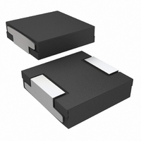
... Max ± INDUCTANCE TOLERANCE SIZE PA CKAG E CODE For technical questions, contact: magnetics@vishay.com Typical Pad Layout 0.542 [13.76] 0.195 [4.95] 0.310 [7.87] 0.520 ± 0.02 [13.2 ± 0.5] 0.091 ± 0.01 [2.3 ± 0.3] 0.185 ± 0.01 [4.7 ± 0.3] ER ...

Page 2

... L 0.40 60 0.30 40 0.20 20 0. For technical questions, contact: magnetics@vishay.com IHLP-5050FD-01 Vishay Dale IHLP-5050FD-01 0.15 µH ΔT ° 100 DC CURRENT (AMPS) IHLP-5050FD-01 0.30 µH ΔT ° CURRENT (AMPS) IHLP-5050FD-01 0.40 µH L ΔT ° CURRENT (AMPS) IHLP-5050FD-01 0.56 µ ...

Page 3

... L 2.5 60 2.0 1.5 40 1.0 20 0.5 0 For technical questions, contact: magnetics@vishay.com IHLP-5050FD-01 0.82 µH ΔT ° CURRENT (AMPS) IHLP-5050FD-01 1.2 µH ΔT ° CURRENT (AMPS) IHLP-5050FD-01 1.8 µH ΔT ° CURRENT (AMPS) IHLP-5050FD-01 3.3 µH Δ ...

Page 4

... Low Profile, High Current Inductor 100 6 ΔT ° 100 9 ΔT ° IHLP-5050FD-01 10 µH 12 ΔT ° CURRENT (AMPS) For technical questions, contact: magnetics@vishay.com IHLP-5050FD-01 Vishay Dale IHLP-5050FD-01 5.6 µH ΔT ° CURRENT (AMPS) IHLP-5050FD-01 8.2 µH ΔT ° CURRENT (AMPS) 100 www.vishay.com 100 100 ...

Page 5

... Information contained herein is intended to provide a product description only. No license, express or implied, by estoppel or otherwise, to any intellectual property rights is granted by this document. Except as provided in Vishay's terms and conditions of sale for such products, Vishay assumes no liability whatsoever, and disclaims any express or implied warranty, relating to sale and/or use of Vishay products including liability or warranties relating to fitness for a particular purpose, merchantability, or infringement of any patent, copyright, or other intellectual property right ...

Related keywords