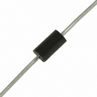
P6KE27CA STMicroelectronics, P6KE27CA Datasheet - Page 3

P6KE27CA
Manufacturer Part Number
P6KE27CA
Description
TRANSIL 600W 27V BIDIR DO-15
Manufacturer
STMicroelectronics
Series
TRANSIL™r
Type
Dioder
Specifications of P6KE27CA
Voltage - Reverse Standoff (typ)
23.1V
Voltage - Breakdown
25.7V
Power (watts)
600W
Polarization
Bidirectional
Mounting Type
Through Hole
Package / Case
DO-204AC, DO-15, Axial
Polarity
Bidirectional
Clamping Voltage
48.3 V
Operating Voltage
23.1 V
Breakdown Voltage
25.7 V
Termination Style
Through Hole
Peak Surge Current
1 mA
Peak Pulse Power Dissipation
600 W
Capacitance
1150 pF
Maximum Operating Temperature
+ 175 C
Minimum Operating Temperature
- 65 C
Dimensions
0.139 in Dia. x 3.53 (Max) mm W x 0.266 in L x 3.53 (Max) mm H
Brand/series
TRANSIL™/P6KE Series
Current, Surge
83 A
Primary Type
Transient Voltage Surge Suppressor
Termination
Solder
Voltage, Clamping
48.3 V
Number Of Elements
1
Package Type
DO-15
Operating Temperature Classification
Military
Reverse Breakdown Voltage
25.7V
Reverse Stand-off Voltage
23.1V
Leakage Current (max)
1uA
Peak Pulse Current
83A
Test Current (it)
1mA
Operating Temp Range
-65C to 175C
Mounting
Through Hole
Pin Count
2
Lead Free Status / RoHS Status
Lead free / RoHS Compliant
For Use With
Industrial Equipment
Available stocks
Company
Part Number
Manufacturer
Quantity
Price
Company:
Part Number:
P6KE27CA
Manufacturer:
STM
Quantity:
10 000
Part Number:
P6KE27CA
Manufacturer:
ST
Quantity:
20 000
Part Number:
P6KE27CA-AU
Manufacturer:
PANJIT/强茂
Quantity:
20 000
Company:
Part Number:
P6KE27CA-E3
Manufacturer:
VISHAY
Quantity:
20 000
Company:
Part Number:
P6KE27CA-E3/54
Manufacturer:
VISHAY
Quantity:
450 000
Company:
Part Number:
P6KE27CA-E3/73
Manufacturer:
RENESAS
Quantity:
1 900
Company:
Part Number:
P6KE27CA-T
Manufacturer:
Diodes Inc
Quantity:
25 499
Figure 1: Pulse waveform (10/1000µs)
Figure 3: Peak pulse power versus exponential
pulse duration
Note 5: The curves of the figure 4 are specified for a junction temperature of 25°C before surge. The given results may be extrapolated for
other junction temperatures by using the following formula :
For intermediate voltages, extrapolate the given results.
Figure 5: Capacitance versus reverse applied
voltage for unidirectional types (typical values)
100
10000
50
1000
0
100
0.001
% I
10
Ppp (W)
1
C (pF)
PP
P 6 K E 6
P 6 K E
P 6 K E 1
P 6 K E 6
0.01
1000µs
2 0 0 A
10µs
V 8 A
8 A
5 A
PULSE WAVEFORM 10/1000µs
0.1
10
1
100
10
F= 1 MHz
Tj = 25°C
V
R
(V)
ø
100
50 0 0
V
BR
t
=
T * [Tamb -25] * V
Figure 2: Peak power dissipation versus initial
junction temperature (printed circuit board)
Figure 4: Clamping voltage versus peak pulse
current (note 5)
Figure 6: Capacitance versus reverse applied
voltage for bidirectional types (typical values)
100
1000
10000
100
80
60
40
20
1000
10
1
0.1
100
0
V
10
CL
0
%
P6KE 440A
P6KE 220A
P6KE 100A
P6KE 68A
P6KE 39A
P6KE 22A
P6KE 12A
P6KE 6V8A
1
(V)
C (pF)
P 6 K E 6 V 8 C A
P 6 K E 1 5 C A
P 6 K E 2 0 0 C
P 6 K E 6 8 C A
20
Exponential waveform:
BR
40
1
(25°C)
A
60
10
80 100 120 140 160 180 200
Tj initial (°C)
t = 20µs
t = 1ms
t = 10ms
p
p
p
10
ø
100
50
0
% Ipp
100
100
t r
F= 1 MHz
Tj = 25°C
Tj initial = 25ø C
t
p
V
R
t < 10
r
Ipp (A)
(V)
P6KE
ø
s
°
50 0 0
1000
t
3/6


