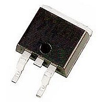
IRG4RC10U International Rectifier, IRG4RC10U Datasheet

IRG4RC10U
Specifications of IRG4RC10U
Available stocks
Related parts for IRG4RC10U
IRG4RC10U Summary of contents
Page 1
... Thermal Resistance Parameter R Junction-to-Case JC R Junction-to-Ambient (PCB mount Weight * When mounted on 1" square PCB (FR-4 or G-10 Material). For recommended footprint and soldering techniques refer to application note #AN-994 www.irf.com PD - 91572A IRG4RC10U UltraFast Speed IGBT C V CES V CE(on) typ 15V n-channel D-PAK TO-252AA Max ...
Page 2
... IRG4RC10U Electrical Characteristics @ T Parameter V Collector-to-Emitter Breakdown Voltage (BR)CES Emitter-to-Collector Breakdown Voltage „ V (BR)ECS Temperature Coeff. of Breakdown Voltage (BR)CES J V Collector-to-Emitter Saturation Voltage CE(ON) V Gate Threshold Voltage GE(th Temperature Coeff. of Threshold Voltage GE(th) J Forward Transconductance … Zero Gate Voltage Collector Current CES ...
Page 3
... Fig Typical Output Characteristics www.irf.com uty c ycle : ° 5° drive cified Typ Frequency (kHz) (Load Current = I of fundamental) RMS 100 150 150 15V Fig Typical Transfer Characteristics IRG4RC10U T ria lam p vo lta rate 50V CC 5µs PULSE WIDTH Gate-to-Emitter Voltage ( ...
Page 4
... IRG4RC10U 100 T , Case Temperature ( C Fig Maximum Collector Current vs. Case Temperature 0.50 1 0.20 0.10 0.05 0.02 SINGLE PULSE 0.01 0.1 (THERMAL RESPONSE) 0.01 0.00001 0.0001 Fig Maximum Effective Transient Thermal Impedance, Junction-to-Case 4 5 15V PULSE WIDTH 4.0 3.0 2.0 1.0 125 150 -60 -40 -20 ° ...
Page 5
... Fig Typical Switching Losses vs. Gate Resistance www.irf.com SHORTED 100 0 Fig Typical Gate Charge vs 0.1 0.01 90 100 -60 -40 -20 ( Fig Typical Switching Losses vs. IRG4RC10U = 400V = 5. Total Gate Charge (nC) G Gate-to-Emitter Voltage 100 = 100Ohm = 15V = 480V 5 2 100 120 140 160 ° Junction Temperature ( ...
Page 6
... IRG4RC10U 1.0 100 R = 100Ohm 150 C ° 480V 15V 0.8 GE 0.6 0.4 0.2 0 Collector-to-emitter Current (A) C Fig Typical Switching Losses vs. Collector-to-Emitter Current L 50V * Driver e Note: Due to the 5 0V pow e r supply, puls e w idth and inductor w ill incre obta in rated Id. ...
Page 7
... B - 0.8 9 (.035 ) 0.6 4 (.025 ) 0 .25 (. TES : SIO N ING & 14 82 SIO 4 -252 SIO +0.16 (. IRG4RC10U Fig. 14b - Switching Loss Waveforms 1.1 4 (.045 ) 0.8 9 (.035 ) 0.58 (.0 23) 0.46 (. (.22 4) LEAD ASSIGNMENTS SIG GATE COLLECTOR ...
Page 8
... IRG4RC10U Tape & Reel Information TO-252AA ILLIM ILL & - LIN -481 . WORLD HEADQUARTERS: 233 Kansas St., El Segundo, California 90245, Tel: (310) 322 3331 IR GREAT BRITAIN: Hurst Green, Oxted, Surrey RH8 9BB, UK Tel 1883 732020 IR GERMANY: Saalburgstrasse 157, 61350 Bad Homburg Tel 6172 96590 IR FAR EAST: K& ...
Page 9
Note: For the most current drawings please refer to the IR website at: http://www.irf.com/package/ ...


