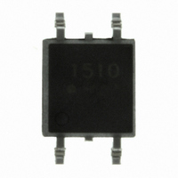
ASSR-1510-003E Avago Technologies US Inc., ASSR-1510-003E Datasheet - Page 10

ASSR-1510-003E
Manufacturer Part Number
ASSR-1510-003E
Description
RELAY HC SPST 1.0A 60V 4-SOP
Manufacturer
Avago Technologies US Inc.
Series
ASSRr
Datasheet
1.ASSR-1510-003E.pdf
(15 pages)
Specifications of ASSR-1510-003E
Package / Case
4-SOP
Termination Style
Gull Wing
Circuit
SPST-NO (1 Form A)
Output Type
AC, DC
On-state Resistance
500 mOhm
Load Current
1A
Voltage - Input
1.3VDC
Voltage - Load
0 ~ 60 V
Mounting Type
Surface Mount
Load Voltage Rating
60 V
Load Current Rating
1 A
Contact Form
1 Form A
Output Device
MOSFET
Mounting Style
SMD/SMT
Relay Type
Solid State
Lead Free Status / RoHS Status
Lead free / RoHS Compliant
Lead Free Status / RoHS Status
Lead free / RoHS Compliant, Lead free / RoHS Compliant
Other names
516-2007
Applications Information
On-Resistance and Derating Curves
The Output On-Resistance, R
sheet, is the resistance measured across the output
contact when a pulsed current signal (Io=1A) is applied
to the output pins. The use of a pulsed signal (≤ 30ms)
implies that each junction temperature is equal to
the ambient and case temperatures. The steady-state
resistance, Rss, on the other hand, is the value of the
resistance measured across the output contact when
a DC current signal is applied to the output pins for
a duration sufficient to reach thermal equilibrium.
Rss includes the effects of the temperature rise in the
device.
Figure 1. Maximum Output Current Rating vs Ambient Temperature
(ASSR-1510-003E)
Figure 3. Maximum Output Current Rating vs Ambient Temperature
(ASSR-1511-001E DC Connection)
10
0.8
0.6
0.4
0.2
1.5
0.5
1
0
2
1
0
-40
-40
I
F
= 10mA, 4-Layer Board
-20
-20
I
F
= 10mA, 4-Layer Board
0
0
T
T
A
A
Operating
Operating
- TEMPERATURE - °C
- TEMPERATURE - °C
Area
Area
Safe
Safe
20
20
(ON)
40
40
, specified in this data
60
60
80
80
100
100
Derating curves are shown in Figures 1, 2, 3 and 4,
specifying the maximum output current allowable for
a given ambient temperature. The maximum allowable
output current and power dissipation are related by the
expression Rss=Po(max)/(Io(max))
be calculated. Staying within the safe area assures that
the steady state MOSFET junction temperature remains
less than 125°C.
Turn On Time and Turn Off Time Variation
The ASSR-15xx Series exhibits a very fast turn on and
turn off time. Both the turn on and turn off time can
be adjusted by choosing proper forward current as
depicted in Figures 12 and 14. The changes of the turn
on and turn off time with ambient temperature are also
shown in Figures 13 and 15.
Figure 2. Maximum Output Current Rating vs Ambient Temperature
(ASSR-1511-001E)
Figure 4. Maximum Output Current Rating vs Ambient Temperature
(ASSR-1520-002E and ASSR-1530-005E)
0.8
0.6
0.4
0.2
1.0
0.8
0.6
0.4
0.2
1
0
0
-40
-40
-20
-20
I
F
Operating
= 10mA, 4-Layer Board
Safe
Area
I
F
0
0
T
= 10mA, 4-Layer Board
2-Channel
A
- TEMPERATURE - °C
T
A
- TEMPERATURE - °C
20
20
Operating
1-Channel
Area
Safe
40
2
40
from which Rss can
60
60
80
80
100
100


