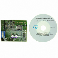
EVAL6730 STMicroelectronics, EVAL6730 Datasheet - Page 27

EVAL6730
Manufacturer Part Number
EVAL6730
Description
EVAL BOARD FOR L6730XX
Manufacturer
STMicroelectronics
Type
Motor / Motion Controllers & Driversr
Datasheets
1.L6730TR.pdf
(52 pages)
2.L6730DTR.pdf
(50 pages)
3.EVAL6730.pdf
(9 pages)
4.EVAL6732.pdf
(43 pages)
Specifications of EVAL6730
Main Purpose
DC/DC, Step Down
Outputs And Type
1, Non-Isolated
Power - Output
66W
Voltage - Output
3.3V
Current - Output
20A
Voltage - Input
4.5 ~ 14V
Regulator Topology
Buck
Frequency - Switching
400kHz
Board Type
Fully Populated
Utilized Ic / Part
L6730
Input Voltage
8 V to 52 V
Product
Power Management Modules
Lead Free Status / RoHS Status
Lead free / RoHS Compliant
For Use With/related Products
L6208
Other names
497-5501
Available stocks
Company
Part Number
Manufacturer
Quantity
Price
A simple circuit to generate two different reference voltages is shown in Figure 29. R
to have
and R
A similar circuit can also be used to modify the reference voltage in other situations. For example it's possible, at con-
stant rotation speed, to reduce the motor torque, and to increase it during acceleration and deceleration. Adding a
second transistor is possible to implement 4 different reference voltages, selectable by two logic signals.
Figure 29. Realizing Half Step current shaping.
Normal and Wave Drive are full step modes. In Wave Drive mode the two motor windings are alternately ener-
gized, while in Normal Drive both the windings are energized in each state, increasing the torque by a factor of
the torque ripple is higher than in normal drive mode.
2.16 Microstepping
Microstepping operation gives several advantages, including the absence of instability phenomena due to low-
torque regions in certain motors' speed-torque diagrams (see Figure 27), reduction of mechanical noise and in-
creased position resolution. The L6208 can be used as two-phase microstepping driver IC [5]. The controller
circuitry allows for an easy and inexpensive design with such device. By controlling the V
to get in the two phases variable output currents with a sine-wave shape. A variable voltage proportional to the
desired output current is applied to each reference pin. For microstepping, the two inputs are rectified sine-wave
voltages with a phase delay of 90°. The L6208 is operated in the normal drive mode and the frequency of the
two sine-wave voltages must be 1/4 of the CLOCK frequency. Figure 30 shows a circuit to generate the two
sine-wave signals using low-pass filters and two PWM outputs of a µC (see Reference Voltage for PWM Current
Control section). Figure 31 shows the V
2
. On the other hand the total current in the motor is double, so the efficiency is similar. In wave drive mode
3
should be
to V
ref
V
pin(s)
re f HIG H
R
R
ref
1
2
GND
+5V
R
voltages, the CLOCK signal and the output currents.
3
=
=
R
--------------------------------------------------- -
3
V
2 1
re f
–
15k
R
1
2
R
=
R
4.7k
2
1
5V
+
R
even numbered states
2
--------------------
R
odd numbered states
0V during
1
R
5V during
+
2
R
AN1451 APPLICATION NOTE
2
1
and R
ref
2
input it is possible
should be chosen
27/43


