USBMLPPCBDM Freescale Semiconductor, USBMLPPCBDM Datasheet

MULTILINK P&E POWERPC USB

USBMLPPCBDM

Manufacturer Part Number
USBMLPPCBDM
Description
MULTILINK P&E POWERPC USB
Manufacturer
Freescale Semiconductor
Series
USB Multilinkr
Type
In Circuit Debuggerr
Datasheet

Specifications of USBMLPPCBDM

Contents
Module and Misc Hardware
Leaded Process Compatible
Yes
Rohs Compliant
Yes
Peak Reflow Compatible (260 C)
Yes
For Use With/related Products
MPC5xx / 55xx
Lead Free Status / RoHS Status
Lead free / RoHS Compliant
P&E Microcomputer Systems, Inc.
P.O. Box 2044, Woburn, MA 01888, USA
http://www.pemicro.com
TEL: (617) 353-9206
FAX: (617) 353-9205
USB-ML-PPCBDM, PowerPC BDM Multilink Rev. B (USB 2.0)
Technical Summary
Document # PE3358, Version 1.1
1. Introduction
2. Usage Of The PowerPC BDM Multilink Interface
3. Driver Installation On Windows XP/2000/2003/Vista
4. Computers Running Windows 95, 98, ME, or NT
5. Using A USB Hub
6. Connecting To The Target
7. Startup Reset Sequence
8. Interface Libraries
9. Firmware Updates
10. Software Packages
11. Rev. A To Rev. B Changes
1.0 Introduction
P&E’ s USB POWERPC BDM MULTILINK Rev. B is a high-speed USB 2.0 interface which provides
access to the Background Debug Mode (BDM) on Freescale PowerPC MPC5xx/8xx processors. It is the
hardware interface between a USB port on a Windows 2000, 2003, XP, or Vista machine and the standard
10-pin “Berg” debug connector on the target. By using the USB PowerPC BDM Multilink, the user can
take advantage of background debug mode to halt normal processor execution and use a PC to control the
processor. The user can then directly control the target’ s execution, read/write registers and memory
values, debug code on the processor, and program internal or external FLASH memory devices by using
the appropriate software packages. The pin-out of the connector as specified by Freescale is:
*P&E does not use the VFLS0 and VFLS1 pins and these do not need to be connected to the header.

Related parts for USBMLPPCBDM

USBMLPPCBDM Summary of contents

Page 1

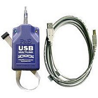
P&E Microcomputer Systems, Inc. TEL: (617) 353-9206 USB-ML-PPCBDM, PowerPC BDM Multilink Rev. B (USB 2.0) 1. Introduction 2. Usage Of The PowerPC BDM Multilink Interface 3. Driver Installation On Windows XP/2000/2003/Vista 4. Computers Running Windows 95, 98, ME ...

Page 2

Usage Of The USB PowerPC BDM Multilink Interface The USB POWERPC BDM MULTILINK can communicate with a PowerPC 5xx/8xx processor. The Multilink interface will work with targets whose processor power supply is in the range of 1.8V to 5.25V. ...

Page 3

Driver Installation On Windows XP/2000/2003/Vista Before connecting the USB PowerPC BDM Multilink to the PC, the appropriate drivers need to be installed on the PC. The drivers are automatically installed when installing any of P&E’ s PowerPC 5xx/8xx development ...

Page 4

If you connected the Multilink interface prior to installing the drivers, Windows will not have been able to find the appropriate driver and may have disabled the device. If you unplug and reconnect the device, Windows will automatically disable it ...

Page 5

Turn the target power on. This should light the Yellow LED on the Multilink. Before disconnecting the setup, turn the target power off. 7.0 Startup Reset Sequence In order to use the Background Debug Mode of the microcontroller, it ...

Page 6

ICDPPCZ – Source-level PowerPC Debugger. This simple and easy to use debugger supports source- level debugging on PowerPC devices including: source-level debug, software load, hardware breakpoints, watch and memory windows, CPU display, special purpose register read/write, and more… PROGPPCZ - ...

Related keywords