702562 Spectrum Digital Inc, 702562 Datasheet
702562
Specifications of 702562


Related parts for 702562


702562 Summary of contents
Page 1
XDS560R JTAG Emulator 2006 Technical Reference DSP Development Systems ...
Page 2
...
Page 3
JTAG Emulator Installation Guide SPECTRUM DIGITAL, INC. 120502 Exchange Drive, #440 Tel: 281.494.4500 sales@spectrumdigital.com XDS560R 507355-0001 Rev. A April 2006 Stafford, TX. 77477 Fax: 281.494.5310 www.spectrumdigital.com ...
Page 4
Spectrum Digital, Inc. reserves the right to make changes to its products or to discontinue any product or service without notice, and advises its customers to obtain the latest version of relevant information to verify, before placing orders, that the ...
Page 5
Introduction to the XDS560R JTAG Emulator Provides an overview of the XDS560R emulator along with the keys features. 1.0 Overview of the XDS560R 1.1 Key Features of the XDS560R 1.2 Key Items on the XDS560R 1.3 Support for Low ...
Page 6
About This Manual This document describes the module level operations of the XDS560R JTAG Emulator. This emulator is designed to be used with digital signal processors (DSPs) and microcontrollers designed by Texas Instruments. The XDS560R JTAG Emulator is a table ...
Page 7
Introduction to the XDS560R This chapter provides you with a description of the XDS560R JTAG Emulator along with the key features. Topic 1.0 Overview of the XDS560R JTAG Emulator 1.1 Key Features of the XDS560R JTAG Emulator 1.2 Key Items ...
Page 8
Spectrum Digital, Inc 1.0 Overview of the XDS560R JTAG Emulator The XDS560R JTAG Emulator is designed to be used with digital signal processors (DSPs) and microprocessors which operate from +1 volt levels on the JTAG interface. The power ...
Page 9
Key Items on the XDS560R JTAG Emulator Figure 1-1 shows the XDS560R. The key items identified are: Power Connector Tail JTAG Connector The XDS560R has vent holes on top. Do NOT: - Obstruct the holes - Insert objects in ...
Page 10
Spectrum Digital, Inc 1-4 XDS560R JTAG Emulator Installation Guide ...
Page 11
Installing the XDS560R This chapter helps you install the XDS560R JTAG Emulator. For use with specific software packages such as the TI’s Code Composer/Studio refer to their respective documentation. Topic 2.1 What You’ll Need Hardware checklist 2.2 Installing the XDS560R ...
Page 12
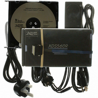
Spectrum Digital, Inc 2.1 What You’ll Need The following checklists detail items that are shipped with the XDS560R JTAG emulator and additional items you’ll need to use these tools. Hardware checklist __ host An IBM PC/AT or 100% compatible PC ...
Page 13
Installing the XDS560R JTAG Emulator This section contains the steps for installing the XDS560R JTAG Emulator. Target Cable Connectors: Be very careful with the target cable connectors. connect them gently; don’t force them into position, or you may damage ...
Page 14
Spectrum Digital, Inc Figures 2-1 and 2-2 show two typical configurations in which the XDS560R can be used with a host PC and target board. USB Cable Plugs into USB port on XDS560R +5 VDC 110/220 VAC Figure 2-1, Connecting ...
Page 15
VAC Power Supply Plugs into USB port USB Hub on Hub and PC/Laptop USB Cable Plugs into a USB port on a Hub Plugs into USB port on XDS560R XDS560R USB +5 VDC Male pin header 110/220 VAC Figure ...
Page 16
Spectrum Digital, Inc 2.3 Connecting the XDS560R to the Target Board The female JTAG connector attached to the end of the emulator tail plugs onto the target’s male pin header. The figure below shows how the XDS560R emulator header plugs ...
Page 17
XDS560R LEDs The XDS560R has five (5) Light Emitting Diodes (LEDs). These LEDs provide the user with the status of the emulator. The position of each LED is shown in the diagram below. The meaning of the LED is ...
Page 18
Spectrum Digital, Inc 2.5 RESET Switch If the emulator becomes non-responsive the unit can be reset by depressing the RESET switch. The RESET switch is recessed and should be depressed with a non-metallic tool. A non-responsive unit exhibits the following ...
Page 19
Specifications For Your Target System’s Connection to the Emulator This chapter contains information about connecting your target system to the emulator. Your target system must use a special 14 or 20-pin connector for proper communication with the emulator. Topic 3.1 ...
Page 20
Spectrum Digital, Inc 3.1 Designing Your Target System’s Emulator Connector (14-pin Header) Certain devices support emulation through a dedicated emulation port. This port is a superset of the IEEE 1149.1 (JTAG) standard and is accessed by the emulator. To perform ...
Page 21
Table 1: 14/20-Pin Header Signal Description Pin # Signal 1 TMS JTAG test mode select. 3 TDI JTAG test data input. 4,8, GND 10,12 7 TDO JTAG test data output. 11 TCK JTAG test clock. TCK is a 12-MHz clock ...
Page 22
Spectrum Digital, Inc 3.2 Bus Protocol The IEEE 1149.1 specification covers the requirements for JTAG bus slave devices (such as the TMS320C5x family) and provides certain rules, summarized as follows: __ The TMS/TDI inputs are sampled on the rising edge ...
Page 23
XDS560R Emulator Cable Pod Logic Figure 3-3 shows a portion of the XDS560R emulator cable pod. The following items are characteristics of the XDS560R pod: ❏ Signals TMS, TDI and TRST are series terminated to reduce signal reflections. ❏ ...
Page 24
Spectrum Digital, Inc To support selection of the proper I/O voltage, the target header has a Target Voltage Detect (TVD) signal. This signal (pin 5) should be tied to the I/O voltage of the target processor. If the target system ...
Page 25
XDS560R Emulator Cable Pod Signal Timing Figure 3-4 shows the default timing waveforms for the XDS560R emulator cable pod. The table below defines the timing parameters. These timing parameters are calculated from values specified in the standard data sheets ...
Page 26
Spectrum Digital, Inc 3.4.1 Emulation Timing Calculations The following examples help you calculate emulation timings in your system. For actual target timing parameters, see the appropriate device data sheet. Assumptions: t su(TTMS) t pd(TTDO) t pd(bufmax) t pd(bufmin) T( bufskew) ...
Page 27
Equation 3-2. Key Timing Path Case 2 Case 2: Single/multiprocessor, TMS/TDI/TCK buffered input, TDO buffered output, TMS/TDI timed from TCK_RET high pd(TCK_RET - TMS/TDI) d(TMSmax 1.35 ns] = 42.35 ns ...
Page 28
Spectrum Digital, Inc 3.5 Connections Between the Emulator and the Target System It is extremely important to provide high-quality signals between the emulator and the JTAG target system. Depending upon the situation, you must supply the correct signal buffering, test ...
Page 29
Importance of Good Design Practices CAUTION The target board designer should use good design practices to minimize signal crosstalk and signal skew. The designer must also take into account any propagation delays of these signals and the effect that they ...
Page 30
Spectrum Digital, Inc 3.5.2 Using a Target-System Clock Figure 3-7 shows an application with the system test clock generated in the target system. In this application, the TCK signal is left unconnected. Vcc I ...
Page 31
Configuring Multiple Processors Figure 3-8 shows a typical series linked multiprocessor configuration, which meets the minimum requirements of the IEEE 1149.1 standard. The emulation signals in this example are buffer to isolate the processor from the emulation and provide ...
Page 32
Spectrum Digital, Inc 3.6 EMU0-EMU1 Signal Considerations The EMU0-EMU1 signals are bi-directional multifunctional signals. These signals are used for software benchmarking and software profiling. On multi-processor systems, they can be used to assist in debugging by causing an interrupt or ...
Page 33
The CBT device could be used to limit the number of devices that the driving EMU0-EMU1 signal is loaded with; thereby limiting the amount of capacitance loading that is seen by the driving EMU0-EMU1 signal. Using this solution would require ...
Page 34
Spectrum Digital, Inc 3.7 Changing Target Cables As new processors are developed different JTAG headers will be required. The XDS560R has a removable target cable (tail) to accommodate these new header requirements. To change the target cable use the following ...
Page 35
Replace the two front panel screws on the XDS560R emulator. If installed properly the retaining plate should not be bowed or bent. ❏ Attach the USB cable to the XDS560R emulator. ❏ Apply Power to the XDS560R emulator. ❏ ...
Page 36
Spectrum Digital, Inc 3.8 Target Cables The XDS560R uses modular target cables that can interchanged for use with specific target JTAG headers. The pin spacing in the cable header may vary from target cable to target cable based on the ...
Page 37
Figure 3-12, 14 Pin Target JTAG Cable The target cable is flexible and about 13 inches long made from micro coax cable. This type of cable has the following flex/bend limitations. 1/8 inch minimum bend diameter Figure 3-13, ...
Page 38
Spectrum Digital, Inc 3.9 Mechanical Dimensions of the XDS560R JTAG Emulator The XDS560R JTAG Emulator consists of a 6-foot USB cable, the XDS560R emulator pod, and a short section of target cable (tail) that connects to the target system. The ...
Page 39
...
Page 40
Printed in U.S.A., April 2006 507355-0001 Rev A ...