RDK-83 Power Integrations, RDK-83 Datasheet
RDK-83
Specifications of RDK-83


Related parts for RDK-83


RDK-83 Summary of contents
Page 1
... The products and applications illustrated herein (including circuits external to the products and transformer construction) may be covered by one or more U.S. and foreign patents or potentially by pending U.S. and foreign patent applications assigned to Power Integrations. A complete list of Power Integrations’ patents may be found at www.powerint.com. ...
Page 2
... Although this board is designed to satisfy safety isolation requirements, the engineering prototype has not been agency approved. Therefore, all testing should be performed using an isolation transformer to provide the AC input to the prototype board. Power Integrations Tel: +1 408 414 9200 Fax: +1 408 414 9201 www.powerint.com ...
Page 3
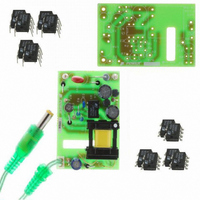
... The report includes the power supply specification, a circuit diagram, a bill of materials, transformer documentation, a printed circuit layout board, and performance data. Figure 1 – Populated Circuit Board Photograph. Page Power Integrations Tel: +1 408 414 9200 Fax: +1 408 414 9201 www.powerint.com ...
Page 4
... Efficiency Full Load Required average efficiency at 25, 50, 75 and 100 % of P OUT Environmental Conducted EMI Safety Surge Differential Mode Common Mode Surge Ambient Temperature Power Integrations Tel: +1 408 414 9200 Fax: +1 408 414 9201 www.powerint.com Symbol Min Typ Max 85 265 50/60 ...
Page 5
... LinkSwitch-LP solution provides a more controlled output characteristic. 18 115 VAC 0.1 0.2 Figure 2 – Output Characteristic Comparison and Limits. Page 0.3 0.4 0.5 Amps Tel: +1 408 414 9200 Fax: +1 408 414 9201 UPPER LIMIT LOWER LIMIT Linear Adapter RD-83 115 VAC 0.6 0.7 0.8 Power Integrations www.powerint.com ...
Page 6
... Schematic Power Integrations Tel: +1 408 414 9200 Fax: +1 408 414 9201 www.powerint.com Figure 3 – Schematic. Page ...
Page 7
... LinkSwitch-LP’s auto-restart function limits output power to about 12% of the maximum. This protects both the load and the supply during prolonged overload conditions. Page The supply easily meets Feedback to the LNK562P IC (U1) is Latching thermal Power Integrations Tel: +1 408 414 9200 Fax: +1 408 414 9201 www.powerint.com ...
Page 8
... V during the 100 ms, the controller disables MOSFET switching. MOSFET switching is alternately enabled and disables at a duty cycle of about 12% until the fault condition clears. This protects both the supply and the load. Power Integrations Tel: +1 408 414 9200 Fax: +1 408 414 9201 www.powerint.com ...
Page 9
... In this design, a fast diode (rather than an ultra-fast) was used for D4 to lower cost and EMI emissions. Page Power Integrations Tel: +1 408 414 9200 Fax: +1 408 414 9201 www.powerint.com ...
Page 10
... L1 and L3, to prevent the breakdown of insulation on those parts. Note: During 10 kV common mode surge testing, no arcing occurred across any of the spark gaps. Figure 4 – RD83 Printed Circuit Layout (2.175” x 1.475” / 55. 37.47 mm). Power Integrations Tel: +1 408 414 9200 Fax: +1 408 414 9201 www.powerint.com (A) ...
Page 11
... N/A Tokin SBCP-47HY102B Yageo MFR-25FBF-22K1 Yageo MFR-25FBF-3K01 Yageo CFR-25JB-4K7 Yageo CFR-25JB-100K Vitrohm CRF253-4 10R Littlefuse V275LA4 Hical Magnetics SIL6043 CWS EP-83 Santronics SNX1388 Taiwan Shulin TF-1613 www.bobbin.com.tw Power Integrations LNK562P Power Integrations Tel: +1 408 414 9200 Fax: +1 408 414 9201 www.powerint.com ...
Page 12
... Magnet Wire: #37 AWG [3] Magnet Wire: #32 AWG [4] Triple Insulated Wire: #30 AWG [5] Tape, 3M 1298 Polyester Film, 2.0 Mils thick wide [6] Varnish [7] Power Integrations Tel: +1 408 414 9200 Fax: +1 408 414 9201 www.powerint.com Primary 3 LAYERS 1 Figure 5 –Transformer Electrical Diagram. 1 second, 60 Hz, from Pins 1-4 to Flying leads Pins 1-2, all other windings open, measured at 100 kHz, 0 ...
Page 13
... Tin leads 0.15”±0.05”. Cut bobbin pins 5,6,7 and 8. trim flying leads Dip varnish assembly with item [7]. Varnish Page Figure 6 – Transformer Build Diagram. Tel: +1 408 414 9200 Fax: +1 408 414 9201 Tape FLYING LEAD FLYING LEAD (MARKED) Tape Shield Tape WD #2 Primary Tape WD #1 Cancellation Power Integrations www.powerint.com ...
Page 14
... CIN 9.40 Input Rectification Type H ENTER LinkSwitch-LP VARIABLES LinkSwitch-LP LNK562 Chosen Device ILIMITMIN ILIMITMAX fSmin Power Integrations Tel: +1 408 414 9200 Fax: +1 408 414 9201 www.powerint.com INFO OUTPUT UNIT ACDC_LinkSwitch-LP_053106_Rev1-12.xls; LinkSwitch-LP Continuous/Discontinuous Flyback Transformer Design Spreadsheet RDR-83 Volts Minimum AC Input Voltage ...
Page 15
... Maximum Duty Cycle 0.04 Amps Average Primary Current 0.12 Amps Minimum Peak Primary Current 0.12 Amps Primary Ripple Current 0.05 Amps Primary RMS Current 3486 uHenries Typical Primary Inductance. +/- 10 Primary inductance tolerance Tel: +1 408 414 9200 Fax: +1 408 414 9201 Power Integrations www.powerint.com ...
Page 16
... PIVS TRANSFORMER SECONDARY DESIGN PARAMETERS (MULTIPLE OUTPUTS) 1st output VO1 IO1 PO1 VD1 NS1 Power Integrations Tel: +1 408 414 9200 Fax: +1 408 414 9201 www.powerint.com 178 Primary Winding Number of Turns 110 nH/T^2 Gapped Core Effective Inductance 1490 Gauss Maximum Operating Flux Density, BM<1500 is ...
Page 17
... Recommended Diodes for this output 0 Cmils Output Winding Bare Conductor minimum circular mils AWG Wire Gauge (Rounded up to next larger standard AWG value) mm Minimum Bare Conductor Diameter mm Maximum Outside Diameter for Triple Insulated Wire Tel: +1 408 414 9200 Fax: +1 408 414 9201 Power Integrations www.powerint.com ...
Page 18
... Total power Negative Output Power Integrations Tel: +1 408 414 9200 Fax: +1 408 414 9201 www.powerint.com 1.63 Watts Total Output Power N/A If negative output exists enter Output number; eg: If VO2 is negative output, enter 2 Page ...
Page 19
... Performance Data All measurements performed at room temperature input frequency. 9.1 Efficiency 100 Efficiency vs. Input Voltage, Room Temperature, 60 Hz. – Figure 7 Page 125 150 175 200 AC Input Voltage (V) Tel: +1 408 414 9200 Fax: +1 408 414 9201 225 250 275 300 Power Integrations www.powerint.com ...
Page 20
... CEC / ENERGY STAR standard. More states within the USA and other countries are adopting this standard. For the latest information, please visit the PI Green Room at: http://www.powerint.com/greenroom/regulations.htm Power Integrations Tel: +1 408 414 9200 Fax: +1 408 414 9201 www.powerint.com Minimum Efficiency in Active Mode of Operation 0.49 × ...
Page 21
... Available Output Power at 1 Watt Input Power vs. Input Voltage. – Figure 9 Page 100 150 200 AC Input Voltage (V) 100 150 200 AC Input Voltage (V) Tel: +1 408 414 9200 Fax: +1 408 414 9201 250 300 250 300 Power Integrations www.powerint.com ...
Page 22
... Regulation 9.4.1 VI Curve vs. Input Voltage 0.1 0.2 Figure 10 – Output VI Curve, Room Temperature. Power Integrations Tel: +1 408 414 9200 Fax: +1 408 414 9201 www.powerint.com 0.3 0.4 0.5 Output Current (A) LOWER LIMIT UPPER LIMIT 115 VAC 85 VAC 230 VAC 265 VAC ...
Page 23
... Figure 11 – Thermal Image of the RD-83 at Full Load, 85 VAC Input and Ambient Temperature of 22 °C. Page Temperature (°C) Item 85 VAC 50 78 Tel: +1 408 414 9200 Fax: +1 408 414 9201 The cardboard box 265 VAC 50 84 Power Integrations www.powerint.com ...
Page 24
... The output was loaded with a 39 Ω resistive load. Figure 14 – Start-up Profile, 115VAC div. The start-up waveforms show minimal output overshoot (<200 mV). Power Integrations Tel: +1 408 414 9200 Fax: +1 408 414 9201 www.powerint.com Figure 13 – 265 VAC, Full Load. Upper ...
Page 25
... Figure 16 – 85 VAC Input and Maximum Load. Upper 0 div. DRAIN Lower 100 V & div. DRAIN Page Figure 17 – 265 VAC Input and Maximum Load. Upper: I Lower: V Tel: +1 408 414 9200 Fax: +1 408 414 9201 , 0 div. DRAIN , 200 V & div. DRAIN Power Integrations www.powerint.com ...
Page 26
... These results were significantly lower than the linear adapter where ripple and transient response variation was greater than 1 V Power Integrations Tel: +1 408 414 9200 Fax: +1 408 414 9201 www.powerint.com Figure 19 – Transient Response, 230 VAC, 50-100- 50% Load Step ...
Page 27
... Figure 21 – Oscilloscope Probe with Probe Master 5125BA BNC Adapter (Modified with wires for probe ground for ripple measurement, and two parallel decoupling capacitors added). Page Probe Ground Probe Tip Power Integrations Tel: +1 408 414 9200 Fax: +1 408 414 9201 www.powerint.com ...
Page 28
... Figure 22 shows increased line frequency ripple. If required, this could be lowered to the level shown in Figure 23 by increasing the value of C6 and C1 to 4.7 µF. Power Integrations Tel: +1 408 414 9200 Fax: +1 408 414 9201 www.powerint.com Figure 23 – Ripple, 115 VAC, Full Load. ...
Page 29
... Unit passed under all test conditions. Page Input Injection Injection Location Phase (°) (VAC) 230 230 230 L,N to RTN 230 L,N to RTN Tel: +1 408 414 9200 Fax: +1 408 414 9201 Test Result (Pass/Fail) 90 Pass 90 Pass 90 Pass 90 Pass Power Integrations www.powerint.com ...
Page 30
... CLRWR -10 -20 150 kHz Figure 26 – Conducted EMI, Maximum Steady State Load, 115 VAC, 60 Hz, and EN55022 B Limits. Power Integrations Tel: +1 408 414 9200 Fax: +1 408 414 9201 www.powerint.com RBW 9 kHz MT 500 ms Att 10 dB AUTO PREAMP OFF 1 MHz LIMIT CHECK MARG ...
Page 31
... Figure 27 – Conducted EMI, Maximum Steady State Load, 230 VAC, 60 Hz, and EN55022 B Limits. Page RBW 9 kHz MT 500 ms Att 10 dB AUTO PREAMP OFF 1 MHz LIMIT CHECK MARG LINE EN55022A MARG LINE EN55022Q MARG Tel: +1 408 414 9200 Fax: +1 408 414 9201 Marker 1 [T1 ] 28.76 dBµV 182.849162999 kHz 10 MHz SGL TDF 30 MHz Power Integrations www.powerint.com ...
Page 32
... Revision History Date Author 29-Sept-06 JAC Power Integrations Tel: +1 408 414 9200 Fax: +1 408 414 9201 www.powerint.com Revision Description & changes 1.0 Initial Release Reviewed PV, JJ, DA Page ...
Page 33
... Page Notes Power Integrations Tel: +1 408 414 9200 Fax: +1 408 414 9201 www.powerint.com ...
Page 34
... Power Integrations Tel: +1 408 414 9200 Fax: +1 408 414 9201 www.powerint.com Notes Page ...
Page 35
... Page Notes Power Integrations Tel: +1 408 414 9200 Fax: +1 408 414 9201 www.powerint.com ...
Page 36
... For the latest updates, visit our website: www.powerint.com Power Integrations reserves the right to make changes to its products at any time to improve reliability or manufacturability. Power Integrations does not assume any liability arising from the use of any device or circuit described herein. POWER INTEGRATIONS MAKES NO WARRANTY HEREIN AND SPECIFICALLY DISCLAIMS ALL WARRANTIES INCLUDING, WITHOUT LIMITATION, THE IMPLIED WARRANTIES OF MERCHANTABILITY, FITNESS FOR A PARTICULAR PURPOSE, AND NON-INFRINGEMENT OF THIRD PARTY RIGHTS ...