MAX3421EVKIT-1+ Maxim Integrated Products, MAX3421EVKIT-1+ Datasheet

EVAL KIT FOR MAX3421E

MAX3421EVKIT-1+

Manufacturer Part Number
MAX3421EVKIT-1+
Description
EVAL KIT FOR MAX3421E
Manufacturer
Maxim Integrated Products
Datasheet

Specifications of MAX3421EVKIT-1+

Main Purpose
Interface, USB 2.0 Host/Controller
Embedded
Yes, MCU, 8-Bit
Utilized Ic / Part
MAX3421E
Primary Attributes
Full Speed (12Mbps), SPI Interface
Secondary Attributes
MAX3420E Provided On-Board as a Test Peripheral
Lead Free Status / RoHS Status
Lead free / RoHS Compliant
The MAX3421 evaluation kit-1 (EV kit-1) provides a
proven design to evaluate the MAX3421E USB periph-
eral controller with SPI™ interface. The EV kit contains
both a MAX3421E USB host & peripheral controller and
a MAX3420E USB peripheral controller for user evalua-
tion and development. Connector J4 is wired to plug
into a Keil MCB2130 development board that contains
a Philips ARM controller (LPC2318). The design uses
two separate SPI ports to provide independent opera-
tion of the two USB controllers (MAX3421E and
MAX3420E).
The MAX3421 EV kit-1 adds USB functionality to any
microcontroller, microprocessor, DSP, CPLD, FPGA, or
ASIC with an SPI master interface, or five GPIO lines.
The EV kit-1 board comes with the MAX3421EEHJ+
and MAX3420EECJ+ installed.
19-0697; Rev 0; 12/06
SPI is a trademark of Motorola, Inc.
For pricing, delivery, and ordering information, please contact Maxim Direct at 1-888-629-4642,
or visit Maxim’s website at www.maxim-ic.com.
DESIGNATION QTY
C1, C3, C5, C6,
C2, C4, C7,
C11–C14
C8, C9
D1–D4
C10
C15
D5
________________________________________________________________ Maxim Integrated Products
6
4
0
1
4
1
2.2µF ±10%, 10V X5R ceramic
capacitors (0805)
TDK C2012X5R1A225KB
1µF ±10%, 16V X5R ceramic
capacitors (0603)
TDK C1608X5R1C105K
Not installed, 18pF ±5%, 50V C0G
ceramic capacitors (0402)
TDK C1005C0G1H180J
0.1µF, 5V (min) X7R ceramic
capacitor (0603)
TDK C1608X7R1C104K,
C1608X7R1E104K, or
C1608X7R1H104K
Panasonic-ECG ECJ-1VB1C104K
KEMET C0603C104K3RAC
AVX 0603ZC104KAT
Green LEDs (0805)
Lumex Opto SML-LX0805UPGC-TR
7-segment LED display,
common-cathode
LITE-ON LSHD-7503
General Description
DESCRIPTION
MAX3421 Evaluation Kit-1
♦ Ideal USB Training and Debugging System
♦ Mates to Keil MCB2130 Development Board
♦ Can Be Wired into User Systems
♦ MAX3421E Can Be Used as a USB Host or
♦ MAX3420E Provided On-Board as a Test
♦ MAX3420E Can be Used to Develop USB
+ Denotes a lead-free and RoHS-compliant EV kit.
DESIGNATION QTY
MAX3421EVKIT-1+
Peripheral
Peripheral
Peripheral Code
PART NUMBER
PB1–PB8
R17, R18
R5–R16
R1–R4
J2, J5
U1
U2
J1
J3
J4
12
1
2
1
1
8
4
2
1
1
Ordering Information
USB type A right-angle receptacle
Assmann Electronic AU-Y1006-R
USB type B right-angle receptacles
Assmann Electronic AU-Y1007-R
3-pin header
2 x 18 right-angle female receptacle
6mm light-touch switches with
GND (H = 7)
Panasonic-ECG EVQ-PBC07K
33Ω ±5% resistors (0603)
470Ω ±5% resistors (0603)
2.2kΩ ±5% resistors (0603)
MAX3421EEHJ+ USB peripheral/host
controller with SPI interface (32-pin,
5mm x 5mm, TQFP)
MAX3420EECJ+ USB peripheral
controller with SPI
interface (32-pin, 7mm x 7mm, TQFP)
TYPE
EV kit
Component List
DESCRIPTION
PC INTERFACE
Features
USB
1

Related parts for MAX3421EVKIT-1+

MAX3421EVKIT-1+ Summary of contents

Page 1

... MAX3421E Can Be Used as a USB Host or Peripheral ♦ MAX3420E Provided On-Board as a Test Peripheral ♦ MAX3420E Can be Used to Develop USB Peripheral Code Ordering Information PART NUMBER MAX3421EVKIT-1+ + Denotes a lead-free and RoHS-compliant EV kit. DESIGNATION QTY USB type A right-angle receptacle J1 1 Assmann Electronic AU-Y1006-R USB type B right-angle receptacles ...

Page 2

... TDK Corp. Note: Indicate that you are using the MAX3421E and MAX3420E when contacting these component suppliers. 2 _______________________________________________________________________________________ Component List (continued) DESIGNATION QTY — 1 MAX3421EVKIT-1+ PCB USB high-speed A-to-B cables, 5ft — 1 (1.5m) Assmann Electronic AU-Y1002A-R 36-pin, dual-row vertical header, with — ...

Page 3

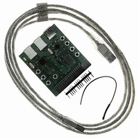
USB TYPE B J5 MAX3420E USB PERIPHERAL CONTROLLER (U2) SPI, POWER Figure 1. Block Diagram Detailed Description The MAX3421 EV kit-1 has three USB connectors (Figure 1). The MAX3421E is wired to USB connectors J1 and J2. Plug a cable ...

Page 4

MAX3421 Evaluation Kit-1 Table 1. J4 Interface to the MAX3420E and MAX3421E J4 PIN MAX3420E 1 3.3V (in) 2 — 3 — 4 — 5 — 6 SCK (in) 7 — 8 MISO (out) 9 — 10 MOSI (in) 11 ...

Page 5

Figure 2a. MAX3421 EV Kit-1 Schematic _______________________________________________________________________________________ MAX3421 Evaluation Kit-1 5 ...

Page 6

MAX3421 Evaluation Kit-1 PB5 PB6 PB7 PB8 GPIN3 GPIN2 D1 470Ω 1 GPOUT0 R7 D2 470Ω 2 ...

Page 7

Figure 3. MAX3421 EV Kit-1 Component Placement Guide—Component Side _______________________________________________________________________________________ MAX3421 Evaluation Kit-1 7 ...

Page 8

MAX3421 Evaluation Kit-1 Figure 4. MAX3421 EV Kit-1 PCB Layout—Component Side 8 _______________________________________________________________________________________ ...

Page 9

... Maxim cannot assume responsibility for use of any circuitry other than circuitry entirely embodied in a Maxim product. No circuit patent licenses are implied. Maxim reserves the right to change the circuitry and specifications without notice at any time. Maxim Integrated Products, 120 San Gabriel Drive, Sunnyvale, CA 94086 408-737-7600 _____________________ 9 © 2006 Maxim Integrated Products MAX3421 Evaluation Kit registered trademark of Maxim Integrated Products, Inc ...

Related keywords