28029 Parallax Inc, 28029 Datasheet - Page 162
28029
Manufacturer Part Number
28029
Description
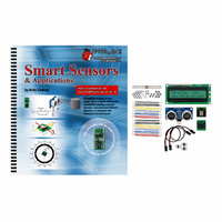
KIT PARTS SMART SENSORS W/TEXT
Manufacturer
Parallax Inc
Datasheet
1.122-28029.pdf
(340 pages)
Specifications of 28029
Accessory Type
Parts Kit
Product
Microcontroller Accessories
Lead Free Status / RoHS Status
Contains lead / RoHS non-compliant
For Use With/related Products
BASIC Stamp® or Javelin Modules
Lead Free Status / RoHS Status
Lead free / RoHS Compliant, Contains lead / RoHS non-compliant
Other names
28029PAR


Page 150 · Smart Sensors and Applications
Board of Education Rev C and USB Board of Education Cable Connections
These instructions are for the boards that have servo ports with a Vdd/Vss jumper in
between, such as the Board of Education Rev C and USB Board of Education. For all
other boards, skip to All other BASIC Stamp Educational Boards on page 151.
√
√
√
√
√
√
Disconnect power to your board.
Set the jumper between the X4 and X5 servo to Vdd (+5 V) as shown in Figure
4-13. The jumper should cover the two pins closest to Vdd, and the third pin
next to Vin should be visible.
Plug one end of the extension cable into Port 14 of the X4 header, making sure
that the "Red" and "Black" labels along the right side of the X5 port line up with
the cable's red and black wires.
Verify that your cable is plugged in correctly by checking to make sure the white
wire is closest to the 14 label and the black wire is closest to the X4 label.
Connect the other end of the cable so that the black wire is connected to the
Parallax Serial LCD's GND pin, the red wire is connected to the 5 V pin, and the
white wire is connected to the RX pin.
Double-check all your connections and make sure they are correct.
Vdd vs. Vin jumper settings determine which power supply is connected to the X4 and X5
ports. When the jumper is set to Vdd, these ports receive regulated 5 V from the Board of
Education's voltage regulator. If the jumper is set to Vin, the port receives power directly
from the battery or power supply. WARNING!! MAKE SURE YOUR JUMPER IS SET
CORRECTLY TO Vdd OR YOU WILL PERMANENTLY DAMAGE YOUR LCD!!
WARNING!
Do not reconnect power to your board until you are positive the connections are
correct. If you make a mistake with the LCD connections, the Parallax Serial LCD will
be permanently damaged.
Figure 4-13
Setting the Servo Port Jumper to Vdd
Related parts for 28029
Image
Part Number
Description
Manufacturer
Datasheet
Request
R


Part Number:
Description:
Microcontroller Modules & Accessories DISCONTINUED BY PARALLAX
Manufacturer:
Parallax Inc

Part Number:
Description:
BOOK UNDERSTANDING SIGNALS
Manufacturer:
Parallax Inc
Datasheet:


Part Number:
Description:
COMPETITION RING FOR SUMOBOT
Manufacturer:
Parallax Inc
Datasheet:


Part Number:
Description:
TEXT INFRARED REMOTE FOR BOE-BOT
Manufacturer:
Parallax Inc
Datasheet:
Part Number:
Description:
BOARD EXPERIMENT+LCD NX-1000
Manufacturer:
Parallax Inc
Datasheet:

Part Number:
Description:
CONTROLLER 16SERVO MOTOR CONTROL
Manufacturer:
Parallax Inc
Datasheet:

Part Number:
Description:
BASIC STAMP LOGIC ANALYZER
Manufacturer:
Parallax Inc
Datasheet:

Part Number:
Description:
IC MCU 2K FLASH 50MHZ SO-18
Manufacturer:
Parallax Inc
Datasheet: