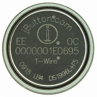
DS1996L-F5+ Maxim Integrated Products, DS1996L-F5+ Datasheet

DS1996L-F5+
Specifications of DS1996L-F5+
Related parts for DS1996L-F5+
DS1996L-F5+ Summary of contents
Page 1
... Easily affixed with self-stick adhesive backing, latched by its flange, or locked with a ring pressed onto its rim Presence detector acknowledges when reader first applies voltage ORDERING INFORMATION PART DS1996L-F5+ +Denotes a lead(Pb)-free/RoHS-compliant package. ® EXAMPLES OF ACCESSORIES ® DS9096P DS9101 DS9093RA ...
Page 2
DESCRIPTION The DS1996 Memory iButton is a rugged read/write data carrier that acts as a localized database that can be easily accessed with minimal hardware. The nonvolatile memory offers a simple solution to storing and retrieving vital information pertaining ...
Page 3
DS1996 BLOCK DIAGRAM Figure DS1996 ...
Page 4
HIERARCHICAL STRUCTURE FOR 1-WIRE PROTOCOL Figure 2 BUS 1-WIRE BUS MASTER COMMAND LEVEL: 1-WIRE ROM FUNCTION COMMANDS (SEE FIGURE 9) DS 1996- SPECIFIC MEMORY FUNCTION COMMANDS (SEE FIGURE 7) 64-BIT LASERED ROM Figure 3 8-Bit CRC Code MSB LSB MSB ...
Page 5
MEMORY The memory map in Figure 5 shows a 32-byte page called the scratchpad and additional 32-byte pages called memory. The DS1996 contains 256 pages which comprise the 65536-bit SRAM. The scratchpad is an additional page that acts as a ...
Page 6
Write Scratchpad Command [0FH] After issuing the write scratchpad command, the master must first provide the 2-byte target address, followed by the data to be written to the scratchpad. The data will be written to the scratchpad starting at the ...
Page 7
MEMORY FUNCTION FLOW CHART Figure TRANSMITTED OR RECEIVED AT OVERDRIVE SPEED IF OD=1 2) RESET PULSE TO BE TRANSMITTED AT OVERDRIVE SPEED IF OD=1; RESET PULSE TO BE TRANSMITTED AT REGULAR SPEED IF OD ...
Page 8
MEMORY FUNCTION EXAMPLES Example: Write two data bytes to memory locations 0026h and 0027h (the seventh and 8th bytes of page 1). Read entire memory. MASTER MODE DATA (LSB FIRST ...
Page 9
Copy Scratchpad [55H] This command is used to copy data from the scratchpad to memory. After issuing the copy scratchpad command, the master must provide a 3-byte authorization pattern which is obtained by reading the scratchpad for verification. This pattern ...
Page 10
HARDWARE CONFIGURATION Figure 8 TRANSACTION SEQUENCE The protocol for accessing the DS1996 via the 1-Wire port is as follows: Initialization ROM Function Command Memory Function Command Transaction/Data INITIALIZATION All transactions on the 1-Wire bus begin with ...
Page 11
Match ROM [55H] The match ROM command, followed by a 64-bit ROM sequence, allows the bus master to address a specific DS1996 on a multidrop bus. Only the DS1996 that exactly matches the 64-bit ROM sequence will respond to the ...
Page 12
SIGNALING The DS1996 requires strict protocols to ensure data integrity. The protocol consists of four types of signaling on one line: Reset Sequence with Reset Pulse and Presence Pulse, Write 0, Write 1 and Read Data. All these signals ...
Page 13
ROM FUNCTIONS FLOW CHART Figure TRANSMITTED OR RECEIVED AT OVERDRIVE SPEED IF OD=1 2) THE PRESENCE PULSE WILL BE SHORT IF OD DS1996 ...
Page 14
ROM FUNCTIONS FLOW CHART Figure 9 (cont’d) 3) ALWAYS TO BE TRANSMITTED AT OVERDRIVE SPEED DS1996 ...
Page 15
INITIALIZATION PROCEDURE “RESET AND PRESENCE PULSES” Figure 10 Regular Speed RESISTOR 480 µs ≤ t 480 µs ≤ t MASTER 15 µs ≤ DS1996 60 µs ≤ order not to mask interrupt signaling by other devices on ...
Page 16
READ/WRITE TIMING DIAGRAM Figure 11 (cont’d) Write-Zero Time Slot Regular Speed 60 µs ≤ µs ≤ t Read-Data Time Slot Regular Speed RESISTOR 60 µs ≤ t MASTER 1 µs ≤ ≤ t DS1996 1 µs ...
Page 17
PHYSICAL SPECIFICATIONS Size Weight Humidity Altitude Expected Service Life ABSOLUTE MAXIMUM RATINGS* Voltage on any Pin Relative to Ground Operating Temperature Storage Temperature ∗ This is a stress rating only and functional operation of the device at these or any ...
Page 18
AC ELECTRICAL CHARACTERISTICS: OVERDRIVE SPEED PARAMETER Time Slot Write 1 Low Time Write 0 Low Time Read Data Valid Release Time Read Data Setup Recovery Time Reset Time High Reset Time Low Presence Detect High Presence Detect Low NOTES: 1. ...
Page 19
... © 2009 Maxim Integrated Products DESCRIPTION spec from 8µs to 7µs in Figure 10 and in the AC spec from 0.8V to 0.3V. IL(MAX Maxim is a registered trademark of Maxim Integrated Products, Inc DS1996 PAGES CHANGED 15, 18 ...


