IL217AT Vishay, IL217AT Datasheet

OPTOCOUPLER PHOTOTRNS 100% 8SOIC

IL217AT

Manufacturer Part Number
IL217AT
Description
OPTOCOUPLER PHOTOTRNS 100% 8SOIC
Manufacturer
Vishay
Datasheet

Specifications of IL217AT

Mounting Type
Surface Mount
Isolation Voltage
4000 Vrms
Number Of Channels
1
Input Type
DC
Voltage - Isolation
4000Vrms
Current Transfer Ratio (min)
100% @ 1mA
Voltage - Output
30V
Current - Dc Forward (if)
60mA
Vce Saturation (max)
400mV
Output Type
Transistor with Base
Package / Case
8-SOIC (3.9mm Width)
Forward Current
60 mA
Maximum Input Diode Current
60 mA
Maximum Reverse Diode Voltage
6 V
Output Device
Transistor With Base
Configuration
1
Maximum Collector Emitter Voltage
30 V
Maximum Collector Emitter Saturation Voltage
400 mV
Current Transfer Ratio
130 % (Typ)
Maximum Forward Diode Voltage
1.5 V
Maximum Collector Current
100 mA
Maximum Power Dissipation
240 mW
Maximum Operating Temperature
+ 100 C
Minimum Operating Temperature
- 55 C
No. Of Channels
1
Optocoupler Output Type
Phototransistor
Input Current
1mA
Output Voltage
30V
Opto Case Style
SOIC
No. Of Pins
8
Number Of Elements
1
Forward Voltage
1.5V
Collector-emitter Voltage
30V
Package Type
SOIC
Collector Current (dc) (max)
100mA
Power Dissipation
240mW
Collector-emitter Saturation Voltage
0.4V
Pin Count
8
Mounting
Surface Mount
Operating Temp Range
-55C to 100C
Operating Temperature Classification
Industrial
Lead Free Status / RoHS Status
Lead free / RoHS Compliant
Current - Output / Channel
-
Current Transfer Ratio (max)
-
Lead Free Status / Rohs Status
Lead free / RoHS Compliant
Other names
751-1288-2
IL217ATGITR
IL217ATGITR

Available stocks

Company
Part Number
Manufacturer
Quantity
Price
Part Number:
IL217AT
Manufacturer:
INFINEON
Quantity:
2 990
Part Number:
IL217AT
Manufacturer:
VISHAY/威世
Quantity:
20 000
IL215AT/216AT/217AT
Vishay Semiconductors
DESCRIPTION
The IL215AT/IL216AT/IL217AT are optically coupled pairs
with a Gallium Arsenide infrared LED and a silicon NPN
phototransistor. Signal information, including a DC level, can
be transmitted by the device while maintaining a high degree
of electrical isolation between input and output. The
IL215AT/IL216AT/IL217AT comes in a standard SOIC-8
small outline package for surface mounting which makes it
ideally suited for high density applications with limited space.
In addition to eliminating through hole requirements, this
package conforms to standards for surface mounted
devices.
The high CTR at low input current is designed for low power
consumption requirements such as CMOS microprocessor
interfaces.
www.vishay.com
324
ORDER INFORMATION
PART
IL215AT
IL216AT
IL217AT
ABSOLUTE MAXIMUM RATINGS
PARAMETER
INPUT
Peak reverse voltage
Forward continuous current
Power dissipation
Derate linearly from 25 °C
OUTPUT
Collector emitter breakdown voltage
Emitter collector breakdown voltage
Collector base breakdown voltage
I
I
Power dissipation
Derate linearly from 25 °C
CMAX DC
CMAX
i179002
Low Input Current, with Base Connection
Optocoupler, Phototransistor Output,
NC
NC
A
K
For technical questions, contact: optocoupler.answers@vishay.com
1
2
3
4
TEST CONDITION
8
7
6
5
t < 1.0 ms
NC
B
C
E
FEATURES
• High current transfer ratio
• Isolation test voltage, 4000 V
• Industry standard SOIC-8 surface mountable
• Compatible with dual wave, vapor phase and
• Lead (Pb)-free component
• Component in accordance to RoHS 2002/95/EC and
AGENCY APPROVALS
• UL1577, file no. E52744 system code Y
• CUL - file no. E52744, equivalent to CSA bulletin 5A
• DIN EN 60747-5-5 available with option 1
package
IR reflow soldering
WEEE 2002/96/EC
SYMBOL
I
CMAX DC
BV
BV
BV
I
P
P
CMAX
V
I
diss
diss
CEO
ECO
CBO
F
R
CTR > 100 %, SOIC-8
CTR > 20 %, SOIC-8
CTR > 50 %, SOIC-8
REMARKS
VALUE
100
150
6.0
1.2
7.0
2.0
60
90
30
70
50
RMS
Document Number: 83616
Rev. 1.9, 08-May-08
mW/°C
mW/°C
UNIT
mW
mW
mA
mA
mA
V
V
V
V

Related parts for IL217AT

IL217AT Summary of contents

Page 1

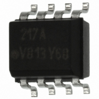
... NC 4 i179002 DESCRIPTION The IL215AT/IL216AT/IL217AT are optically coupled pairs with a Gallium Arsenide infrared LED and a silicon NPN phototransistor. Signal information, including a DC level, can be transmitted by the device while maintaining a high degree of electrical isolation between input and output. The IL215AT/IL216AT/IL217AT comes in a standard SOIC-8 small outline package for surface mounting which makes it ideally suited for high density applications with limited space ...

Page 2

... µ µ =1 TEST CONDITION PART SYMBOL IL215AT CTR I = 1.0 mA 5.0 V IL216AT CTR F CE IL217AT CTR TEST CONDITION PART SYMBOL = 100 Ω, = 2.0 mA IL215AT/216AT/217AT Vishay Semiconductors VALUE 4000 240 tot 3 150 - 100 10 SYMBOL MIN. TYP. MAX. V 1.0 1 0.1 100 ...

Page 3

... 1.0 0.5 0.0 0 LED Current (mA) iil215at_02 F Fig Normalized Non-Saturated and Saturated CTR LED Current www.vishay.com For technical questions, contact: optocoupler.answers@vishay.com 326 Optocoupler, Phototransistor Output, Low Input Current, with Base Connection TEST CONDITION SYMBOL CTI per IEC 60950 2.10.5.1 10 100 0 100 vs. ...

Page 4

... Ib - Base Current (µA) iil215at_07 Fig Normalized Saturated h Base Current and Temperature Document Number: 83616 For technical questions, contact: optocoupler.answers@vishay.com Rev. 1.9, 08-May-08 Optocoupler, Phototransistor Output, 100 iil215at_08 Fig Normalized Non-Saturated and Saturated CTR 80 100 iil215at_09 Fig Normalized Non-Saturated and Saturated Collector Emitter ...

Page 5

... V iil215at_13 Fig Low to High Propagation Delay vs. LED Current and Load Resistor www.vishay.com For technical questions, contact: optocoupler.answers@vishay.com 328 Optocoupler, Phototransistor Output, Low Input Current, with Base Connection 100 1000 1 Fig Typical Switching Times vs. Load Resistance 1.2 70 °C Normalized to: 50 ° ...

Page 6

... Pin one ID 0.192 ± 0.005 (4.88 ± 0.13) 0.004 (0.10) 0.008 (0.20) 0.021 (0.53) ISO method A i178003 Document Number: 83616 For technical questions, contact: optocoupler.answers@vishay.com Rev. 1.9, 08-May-08 Optocoupler, Phototransistor Output, Input pdon OUT ...

Page 7

... The Montreal Protocol (1987) and its London Amendments (1990) intend to severely restrict the use of ODSs and forbid their use within the next ten years. Various national and international initiatives are pressing for an earlier ban on these substances. Vishay Semiconductor GmbH has been able to use its policy of continuous improvements to eliminate the use of ODSs listed in the following documents. ...

Page 8

... Vishay disclaims any and all liability arising out of the use or application of any product described herein or of any information provided herein to the maximum extent permitted by law. The product specifications do not expand or otherwise modify Vishay’ ...

Related keywords