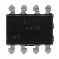
6N135S Lite-On Electronics, 6N135S Datasheet - Page 9

6N135S
Manufacturer Part Number
6N135S
Description
OPTOCOUPLER HS TRANS OUT 8-SMD
Manufacturer
Lite-On Electronics
Datasheet
1.6N135S-TA1.pdf
(10 pages)
Specifications of 6N135S
Input Type
DC
Package / Case
8-SMD Gull Wing
Voltage - Isolation
5000Vrms
Number Of Channels
1, Unidirectional
Current - Output / Channel
8mA
Data Rate
1Mbps
Propagation Delay High - Low @ If
800ns @ 16mA
Current - Dc Forward (if)
25mA
Output Type
Open Collector
Mounting Type
Surface Mount
Isolation Voltage
5000 Vrms
Output Device
Phototransistor
Configuration
1 Channel
Current Transfer Ratio
50 %
Maximum Baud Rate
1 MBps
Maximum Forward Diode Voltage
1.7 V
Maximum Reverse Diode Voltage
5 V
Maximum Input Diode Current
25 mA
Maximum Power Dissipation
100 mW
Maximum Operating Temperature
+ 70 C
Minimum Operating Temperature
0 C
Lead Free Status / RoHS Status
Lead free / RoHS Compliant
Other names
160-1785
Available stocks
Company
Part Number
Manufacturer
Quantity
Price
Part Number:
6N135SD
Manufacturer:
FAIRCHILD/仙童
Quantity:
20 000
BNS-OD-C131/A4
Part No. : 6N135 / 6N136 Series (Preliminary Date Sheet)
6 Isolation Resistance ( Input-output )
6 Capacitance ( Input-output )
ISOLATION CHARACTERISTICS
2. For 10 Seconds
4. Add a 0.1uF bypass capacitor connected between pin5 and pin8 is recommended.
5. Common transient immunity in logic high level is the maximum tolerance (positive)
** All typical at T
Notes,
6. Device considered a two terminal device. Pins 1, 2, 3 and 4 shorted together and Pins 5, 6,
7. The 4.1
8.
1. AC For 1 Minute, R.H. = 40 ~ 60%
3. Current Transfer Ratio (CTR) is defined as the ration of output collector current, Io,
to the forward LED input current, IF, times 100%.
Isolation voltage shall be measured using the following method.
(1) Short between anode and cathode on the primary side and between collector and
(2) The isolation voltage tester with zero-cross circuit shall be used.
(3) The waveform of applied voltage shall be a sine wave.
dV
output will remain in a logic high state (i.e., Vo>2.0V). Common mode transient
immunity in a logic low level is the maximum tolerance (negative) dV
edge of the common mode pulse signal, VCM, to assure that the output will remain in a
logic low state (i.e., Vo<0.8V).
7 and 8 shorted together.
The 1.9
emitter on the secondary side.
CM
/dt on the leading edge of the common mode pulse signal, V
PARAMETER
kΩ load represents 1 LSTTL unit load of 0.36mAand 6.1 kΩ pull up resistor.
kΩ load represents 1 TTL unit load of 1.6mAand 5.6 kΩ pull up resistor.
A
= 25℃
LITE-ON TECHNOLOGY CORP.
Property of Lite-on Only
SYMBOL MIN. TYP. MAX. UNIT
R
C
I-O
I-O
—
—
10
0.6
12
—
—
CM
pF
, to assure that the
CM
/dt on the teailing
Ta=25℃, RH<45%,
f=1MHz
V
I-O
Page :
CONDITIONS
=500V DC
9 of 10


