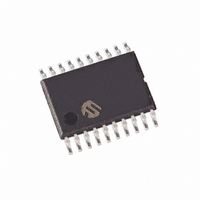
MCP1631HV-500E/ST Microchip Technology, MCP1631HV-500E/ST Datasheet - Page 45

MCP1631HV-500E/ST
Manufacturer Part Number
MCP1631HV-500E/ST
Description
IC INTEGRATED PWM HS 20TSSOP
Manufacturer
Microchip Technology
Datasheets
1.MCP1631VHVT-330EST.pdf
(34 pages)
2.MCP1631VHVT-330EST.pdf
(32 pages)
3.MCP1631HV-330EST.pdf
(54 pages)
4.MCP1631-EST.pdf
(32 pages)
Specifications of MCP1631HV-500E/ST
Package / Case
20-TSSOP
Pwm Type
Current Mode
Number Of Outputs
1
Frequency - Max
2MHz
Duty Cycle
10%
Voltage - Supply
3.5 V ~ 16 V
Buck
Yes
Boost
No
Flyback
No
Inverting
No
Doubler
No
Divider
No
Cuk
No
Isolated
Yes
Operating Temperature
-40°C ~ 125°C
Frequency-max
2MHz
Output Voltage
3.3 V to 5 V
Output Current
250 mA
Input Voltage
3 V to 5.5 V
Switching Frequency
2 MHz
Operating Temperature Range
- 40 C to + 125 C
Mounting Style
SMD/SMT
Frequency
1MHz
Digital Ic Case Style
TSSOP
No. Of Pins
20
Peak Reflow Compatible (260 C)
Yes
Rohs Compliant
Yes
Leaded Process Compatible
Yes
Lead Free Status / RoHS Status
Lead free / RoHS Compliant
For Use With
MCP1631RD-DCPC1 - REF DES BATT CHARG OR LED DRIVERMCP1631RD-MCC2 - REFERENCE DESIGN MCP1631HV
Lead Free Status / Rohs Status
Lead free / RoHS Compliant
© 2009 Microchip Technology Inc.
24. Press and hold the “ON/OFF” button on the charger board until the LED’s flash
25. Press and release the “CHEM” button until the “Li-Ion” LED is on.
26. Press and release the “# CELLS” button until the “0” display LED is on and the
27. Press and hold the “# CELLS” button on the charger board until the LED’s flash
28. Press the “ON/OFF” button. The charger will exit Configuration mode.
29. Turn off and disconnect the power supply.
30. Reconnect the variable supply (+) lead to the input connector (+) pin J1-1.
31. Reconnect the variable supply (-) lead to the input connector (-) pin J1-2.
32. Connect the Li-Ion battery pack to the charger board J2 connector.
33. Turn on the supply and set the voltage to 8.0V (any voltage between 6V and 12V
34. Press the “ON/OFF” button. The charger will start charging the battery.
35. Press the “CHEM” button to display the current charger state in HEX. “0” LED is
36. Press the “# CELLS” button to display the termination cause. No LED means no
37. Using an oscilloscope, refer to A.2 “Board – Schematic” and A.3 “Board – Top
38. Press the “ON/OFF” button. The charger will stop charging the battery.
(about 5 seconds). The board is now in Configuration Mode.
“1,2,3” display LED’s are off.
(about 5 seconds). The board is now calibrated to use the 4.200V as the Li-Ion
battery voltage.
is good).
the LS Bit.
premature termination.
Silk Layer” and probe the following components:
- V
- PWM = TP4
- Oscillator = TP5
- VS
- Slope Compensation = TP7
- Temperature = TP8 (if used)
- FB = TP9
- Drain Voltage = TP10
- Output Voltage = TP11
REF
OUT
= TP3
= TP6
Software
DS51791A-page 41


