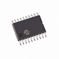
MCP1631HV-500E/ST Microchip Technology, MCP1631HV-500E/ST Datasheet - Page 10

MCP1631HV-500E/ST
Manufacturer Part Number
MCP1631HV-500E/ST
Description
IC INTEGRATED PWM HS 20TSSOP
Manufacturer
Microchip Technology
Datasheets
1.MCP1631VHVT-330EST.pdf
(34 pages)
2.MCP1631VHVT-330EST.pdf
(32 pages)
3.MCP1631HV-330EST.pdf
(54 pages)
4.MCP1631-EST.pdf
(32 pages)
Specifications of MCP1631HV-500E/ST
Package / Case
20-TSSOP
Pwm Type
Current Mode
Number Of Outputs
1
Frequency - Max
2MHz
Duty Cycle
10%
Voltage - Supply
3.5 V ~ 16 V
Buck
Yes
Boost
No
Flyback
No
Inverting
No
Doubler
No
Divider
No
Cuk
No
Isolated
Yes
Operating Temperature
-40°C ~ 125°C
Frequency-max
2MHz
Output Voltage
3.3 V to 5 V
Output Current
250 mA
Input Voltage
3 V to 5.5 V
Switching Frequency
2 MHz
Operating Temperature Range
- 40 C to + 125 C
Mounting Style
SMD/SMT
Frequency
1MHz
Digital Ic Case Style
TSSOP
No. Of Pins
20
Peak Reflow Compatible (260 C)
Yes
Rohs Compliant
Yes
Leaded Process Compatible
Yes
Lead Free Status / RoHS Status
Lead free / RoHS Compliant
For Use With
MCP1631RD-DCPC1 - REF DES BATT CHARG OR LED DRIVERMCP1631RD-MCC2 - REFERENCE DESIGN MCP1631HV
Lead Free Status / Rohs Status
Lead free / RoHS Compliant
MCP1631HV Multi-Chemistry Battery Charger Reference Design
1.2
1.3
DS51791A- page 6
WHAT IS THE MCP1631HV MULTI-CHEMISTRY BATTERY CHARGER
REFERENCE DESIGN?
WHAT THE MCP1631HV MULTI-CHEMISTRY BATTERY CHARGER
REFERENCE DESIGN KIT INCLUDES
The MCP1631HV Multi-Chemistry Battery Charger is a complete stand-alone battery
charger for NiMH, NiCd or Li-Ion battery packs. The board may also be used to drive
LED devices using constant current mode. When charging NiMH or NiCd batteries the
reference design is capable of charging one to five batteries connected in series. If
Li-Ion chemistry is selected, the board is capable of charging one or two series
batteries. When the LED driver is selected, the board is capable of driving one to two
1W LEDs. This board utilizes Microchip’s MCP1631HV (high-speed PWM and
PIC16F883 MCU). The input voltage range for the demo board is 5.3V to 16V.
The board is capable of both boosting and bucking the input voltage in order to obtain
the desired output voltage because a SEPIC converter topology is used. The overvolt-
age limit for the board is set to 9V. The powertrain components may be changed to
allow for higher output voltages and power.
TABLE 1-1:
An input terminal block is provided to apply the input voltage to the charger. An output
header is also provided as a means to connect the external battery pack or simulated
battery load and external 10K thermistor. A programming header is available for
updating the firmware contained in the PIC16F883.
This MCP1631HV Multi-Chemistry Battery Charger Reference Design kit includes:
• The MCP1631HV Multi-Chemistry Battery Charger Board,102-00232
• Analog and Interface Products Demonstration Boards CD-ROM includes
Li-Ion
NiMH or NiCd
LED Driver
(DS21912):
- MCP1631HV Multi-Chemistry Battery Charger User’s Guide, (DS51697).
- MCP1631 Data Sheet, “High-Speed, Microcontroller-Adaptable, Pulse Width
- PIC16F883 Data Sheet, “8-Pin Flash-Based, 8-Bit CMOS Microcontrollers
- Application Note AN1137, “Using the MCP1631 Family to Develop Low-Cost
Battery Chemistry
Modulator”, (DS22063).
with nanoWatt Technology”, (DS41291).
Battery Chargers”, (DS01137).
MULTI-CHEMISTRY CHARGER CAPABILITY
300 mA
1 Cell
1.5A
2A
300 mA
2 Cell
1.5A
1A
3 Cell
1.5A
NA
NA
© 2009 Microchip Technology Inc.
4 Cell
1.5A
NA
NA
5 Cell
1.5A
NA
NA


