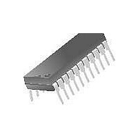
KA3511DS Fairchild Semiconductor, KA3511DS Datasheet - Page 15

KA3511DS
Manufacturer Part Number
KA3511DS
Description
IC PWM/SECONDARY COMBO 22-DIP
Manufacturer
Fairchild Semiconductor
Datasheet
1.KA3511DS.pdf
(28 pages)
Specifications of KA3511DS
Pwm Type
Current Mode
Number Of Outputs
3
Frequency - Max
10kHz
Duty Cycle
50%
Voltage - Supply
14 V ~ 30 V
Buck
No
Boost
No
Flyback
No
Inverting
No
Doubler
No
Divider
No
Cuk
No
Isolated
No
Operating Temperature
-25°C ~ 85°C
Package / Case
22-DIP (0.400", 10.16mm)
Frequency-max
10kHz
Topology
Push-Pull
Output Voltage
40 V
Output Current
200 mA
Switching Frequency
10 KHz
Maximum Operating Temperature
+ 85 C
Minimum Operating Temperature
- 25 C
Fall Time
50 ns
Mounting Style
Through Hole
Rise Time
100 ns
Synchronous Pin
No
Lead Free Status / RoHS Status
Lead free / RoHS Compliant
Available stocks
Company
Part Number
Manufacturer
Quantity
Price
Company:
Part Number:
KA3511DS
Manufacturer:
NMB
Quantity:
2 000
6.8 R/S FLIP FLOP (LATCH) BLOCK
There is a R-S F/F (Latch) circuit for shutdown operation in the KA3511. R-S F/F (Latch) is con-
trolled by OVP, UVP, and some delayed remote ON/OFF signal.
If any output of OVP or UVP is High, SET signal of R-S F/F is high status and it produces PWM
“High” and main power is turned off. When remote signal is high, its delayed output signal is sup-
plied to RESET port of R-S F/F and it produces SET low. So output Q is low status. At this time,
PWM maintains high status by delayed remote high signal.
After main power is turned-off by OVP/UVP and initialized by remote, if remote signal is changed to
low, main power becomes operational.
When you test KA3511, Remote ON/OFF signal should be toggled once for initializing.
OVP+
High
High
Low
Low
High
SET
Low
Low
Low
Figure 10. R-S F/F Block Diagram
RESET
High
High
Low
Low
15
Qn+1
High
High
Low
Qn
Rev C, November 1999
Qn+1
High
High
Low
Qn


