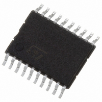
STMEC001ATTR STMicroelectronics, STMEC001ATTR Datasheet - Page 5

STMEC001ATTR
Manufacturer Part Number
STMEC001ATTR
Description
IC POWER SWITCH EXPRESS 20-TSSOP
Manufacturer
STMicroelectronics
Datasheet
1.STMEC001ATTR.pdf
(19 pages)
Specifications of STMEC001ATTR
Operating Temperature
-40°C ~ 120°C
Mounting Type
Surface Mount
Package / Case
20-TSSOP
Lead Free Status / RoHS Status
Lead free / RoHS Compliant
Current - Supply
-
Voltage - Supply
-
Applications
-
Other names
497-8022-2
STMEC001ATTR
STMEC001ATTR
Available stocks
Company
Part Number
Manufacturer
Quantity
Price
STMEC001
1.1
Pin functional description
Table 3.
RCLKEN
Symbol
SYSRST
CPUSB
PERST
SHDN
CPPE
STBY
OC
A logic low level on this input indicates that the card present supports PCI Express
functions. This input pin connects to the 3.3 V
When inserted, the card physically connects this input to ground if the card supports PCI
Express functions.
A logic low level on this input indicates that the card present supports USB functions. The
input pin CPUSB connects to the 3.3 V
inserted, the card physically connects CPUSB to ground if the card supports USB
functions.
When asserted (logic low), this input instructs the STMEC001 to turn off all voltage
outputs and the discharge FETs at the 3 outputs are activated.
When asserted (logic low), this input places the power switch in Standby Mode by turning
off the 3.3 V and 1.5 V power switches and keeping the 3.3 V
This pin serves as both an input and an output. On power up, the power switch keeps this
signal at a low state as long as any of the output power rails are out of their tolerance
range. Once all output power rails are within tolerance, the power switch releases
RCLKEN allowing it to transition to a high state (internally pulled up to 3.3 V
transition of RCLKEN from a low to a high state starts an internal timer for the purpose of
de-asserting /PERST. As an input, RCLKEN can be kept low to delay the start of the
/PERST internal timer. RCLKEN can be used by the host system to enable a clock driver.
On power up, this output remains asserted. Once all power rails are within tolerance,
RCLKEN is asserted and /PERST is de-asserted after a time delay. On power down, this
output is asserted whenever any of the power rails drop below their voltage tolerance.
This input is driven by the host system and directly affects /PERST. Asserting /SYSRST
(logic level: low) forces /PERST to assert.
The OC pin is an open drain output for over-current indication. Output does not turn off
during over-current condition. The output voltage decreases as the output current
exceeds over-current limit. Only if the temperature increases above the limit the output is
turned off completely. Over-current in one output does not affect the other outputs.
Pin detailed descriptions
Description
AUX
input through a 150 kΩ internal pull up. When
AUX
input through a 150 kΩ internal pull up.
AUX
switch on.
Pin description
AUX
). The
5/19


