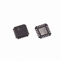
ISL6111CR Intersil, ISL6111CR Datasheet - Page 12

ISL6111CR
Manufacturer Part Number
ISL6111CR
Description
IC CTRLR HOT PLUG SWITCH 20-QFN
Manufacturer
Intersil
Type
Hot-Swap Controllerr
Datasheet
1.ISL6111CRZA.pdf
(16 pages)
Specifications of ISL6111CR
Applications
PCI, PCI-X
Internal Switch(s)
Yes
Voltage - Supply
3.3V, 5V, 12V
Operating Temperature
0°C ~ 85°C
Mounting Type
Surface Mount
Package / Case
20-VQFN Exposed Pad, 20-HVQFN, 20-SQFN, 20-DHVQFN
Lead Free Status / RoHS Status
Contains lead / RoHS non-compliant
Typical Performance Curves & Waveforms
Using the ISL6111EVAL2 Platform
Biasing and General Information
The ISL6111EVAL2 platform (Figure 20) allows a designer to
evaluate and modify the performance and functionality of the
ISL6111 in a simple environment. The board is made such
that the heat dissipating resistors are shielded from users and
equipment by being placed on the bottom, despite this the top
of the load board still gets hot.
Test point names correspond to the ISL6111 device (U1) pins.
Along with the ISL6111 on the ISL6111EVAL2 platform are 2
N-Channel power MOSFETs, (Q1- Q2) these are used as the
external switches for the +5V and +3.3V supplies to the load.
Current sensing is facilitated by the two 5mΩ 1W metal strip
resistors (R7, R3), the voltages developed across the sense
resistors are compared to references on board the ISL6111.
The ISL6111EVAL2 platform is powered through the 5 labeled
jacks on the left half of the board, with outputs on the right
half. After properly biasing the ISL6111, signal the ENABLE
input high (>2.4V), this will turn on the FET switches and
apply voltage to the loads resistors and capacitors.
Voltage and current measurements can be easily made as
the test points facilitate access to IC pins and other critical
circuit nodes.
101
100
99
98
97
FIGURE 12. CRSET CURRENT vs TEMPERATURE
0
25
TEMPERATURE (°C)
12
50
75
85
ISL6111
(Continued)
Evaluating Current Regulation Duration
The current regulation (CR) duration is set by the CRTIM
capacitor value, C3 to ground. This provides a programmable
duration during which the ISL6111 holds the programmed CR
level. Once this duration has expired and the ISL6111 is still in
CR mode the output voltages will turn off.
The intent of any protection device is to quickly isolate the
voltage supplies so a faulty load card does not drag down a
supply. A duration period too lengthy increases the likelihood
of FET switch damage and results in slower isolation of the
faulty card from the rest of system.
Figures 14 -19 show nominal turn-on, turn-on into OC
condition with CR mode waveforms.
FIGURE 13. CRTIM THRESHOLD VOLTAGE vs
2.72
2.74
2.68
2.70
0
TEMPERATURE
25
TEMPERATURE (°C)
50
75
85


