LM2405T National Semiconductor, LM2405T Datasheet - Page 3
LM2405T
Manufacturer Part Number
LM2405T
Description
IC DRIVER MONOLITHIC TO-220-11
Manufacturer
National Semiconductor
Datasheet
1.LM2405T.pdf
(7 pages)
Specifications of LM2405T
Display Type
CRT
Current - Supply
18mA
Voltage - Supply
60 V ~ 85 V
Operating Temperature
-20°C ~ 100°C
Mounting Type
Through Hole
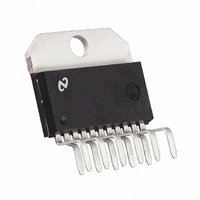
Package / Case
TO-220-11 (Bent and Staggered Leads)
Lead Free Status / RoHS Status
Contains lead / RoHS non-compliant
Interface
-
Configuration
-
Digits Or Characters
-
Other names
*LM2405T
Available stocks
Company
Part Number
Manufacturer
Quantity
Price

Part Number:
LM2405T
Manufacturer:
NS/国半
Quantity:
20 000
Company:
Part Number:
LM2405T(EM89DT)
Manufacturer:
NationalSemi
Quantity:
308


AC Test Circuit
(Continued)
DS012682-7
FIGURE 6. Pulse Response
Theory of Operation
DS012682-4
The LM2405 is a high voltage monolithic triple CRT driver
FIGURE 3. V
vs V
OUT
IN
suitable for SVGA and XGA display applications. The
LM2405 features +80V operation and low power dissipation.
The part is housed in the industry standard 11-lead TO-220
molded plastic power package.
The circuit diagram of the LM2405 is shown in Figure 1 . A
PNP emitter follower, Q5, provides input buffering. Q1 and
Q2 form a fixed gain cascode amplifier, with a gain of −14.
Emitter followers Q3 and Q4 isolate the high output imped-
ance of the amplifier from the capacitance of the CRT cath-
ode, and make the circuit relative insensitive to load capaci-
tance. Q6 provides biasing to the output emitter follower
stage to reduce crossover distortion at low signal levels.
Figure 2 shows a typical test circuit for evaluation of the
LM2405. This circuit is designed to allow testing of the
LM2405 in a 50
environment, such as a pulse generator
and a scope, or a network analyzer. In this test circuit, two
low inductance resistors in series totaling 4.95 k
form a
DS012682-5
100:1 wideband low capacitance probe when connected to a
FIGURE 4. Power Dissipation vs V
50
cable and load. The input signal from the generator is
CC
AC coupled to the base of Q5.
Application Hints
INTRODUCTION
National Semiconductor is committed to providing applica-
tion information that assists our customers in obtaining the
best performance possible from our products. The following
information is provided in order to support this commitment.
The reader should be aware that the optimization of perfor-
mance was done using a specific printed circuit board de-
signed at National. Variations in performance can be realized
due to physical changes in the printed circuit board and the
application. Therefore, the designer should be aware that
DS012682-6
component value changes may be required in order to opti-
FIGURE 5. Large Signal Frequency Response
mize performance in a given application. The values shown
in this document can be used as a starting point for evalua-
tion purposes. When working with high bandwidth circuits,
good layout practices are also critical to achieving maximum
performance.
POWER SUPPLY BYPASS
Since the LM2405 is a wide bandwidth amplifier, proper
power supply bypassing is critical for optimum performance.
Improper power supply bypassing can result in large over-
shoot, ringing and oscillation. A 0.01 µF capacitor should be
connected from the supply pin, V
, to ground, as close to
CC
3
www.national.com
Related parts for LM2405T
Image
Part Number
Description
Manufacturer
Datasheet
Request
R

Part Number:
Description:
Monolithic Triple 3 ns CRT Driver
Manufacturer:
National Semiconductor
Datasheet:
Part Number:
Description:
National Semiconductor [8-Bit D/A Converter]
Manufacturer:
National Semiconductor
Datasheet:
Part Number:
Description:
National Semiconductor [Media Coprocessor]
Manufacturer:
National Semiconductor
Datasheet:
Part Number:
Description:
Digitally Controlled Tone and Volume Circuit with Stereo Audio Power Amplifier, Microphone Preamp Stage and National 3D Sound
Manufacturer:
National Semiconductor
Datasheet:
Part Number:
Description:
Digitally Controlled Tone and Volume Circuit with Stereo Audio Power Amplifier, Microphone Preamp Stage and National 3D Sound
Manufacturer:
National Semiconductor
Datasheet:
Part Number:
Description:
AC97 Rev 2 Codec with Sample Rate Conversion and National 3D Sound
Manufacturer:
National Semiconductor
Part Number:
Description:
Manufacturer:
National Semiconductor
Datasheet:
Part Number:
Description:
Manufacturer:
National Semiconductor
Datasheet:
Part Number:
Description:
General Purpose, Low Voltage, Low Power, Rail-to-Rail Output Operational Amplifiers
Manufacturer:
National Semiconductor
Datasheet:
Part Number:
Description:
8-bit 20 MSPS flash A/D converter.
Manufacturer:
National Semiconductor
Datasheet:
Part Number:
Description:
Low Noise Quad Operational Amplifier
Manufacturer:
National Semiconductor
Datasheet:
Part Number:
Description:
Quad Differential Line Receivers
Manufacturer:
National Semiconductor
Datasheet:
Part Number:
Description:
Quad High Speed Trapezoidal? Bus Transceiver
Manufacturer:
National Semiconductor
Datasheet:
Part Number:
Description:
Dual Line Receiver
Manufacturer:
National Semiconductor
Datasheet: