ICL7136CPLZ Intersil, ICL7136CPLZ Datasheet
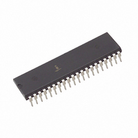
IC ADC 3.5DIGIT LCD LP 40DIP

ICL7136CPLZ

Manufacturer Part Number
ICL7136CPLZ
Description
IC ADC 3.5DIGIT LCD LP 40DIP
Manufacturer
Intersil
Datasheet

Specifications of ICL7136CPLZ

Display Type
LCD
Configuration
7 Segment
Digits Or Characters
A/D 3.5 Digits
Current - Supply
70µA
Voltage - Supply
4 V ~ 6 V
Operating Temperature
0°C ~ 70°C
Mounting Type
Through Hole
Package / Case
40-DIP (0.600", 15.24mm)
Package
40PDIP
Resolution
3 1/2 Digit
Sampling Rate
3 SPS
Architecture
Dual Slope
Number Of Analog Inputs
1
Digital Interface Type
LCD
Input Type
Voltage
Polarity Of Input Voltage
Bipolar
Lead Free Status / RoHS Status
Lead free / RoHS Compliant
Interface
-

Available stocks

Company
Part Number
Manufacturer
Quantity
Price
Part Number:
ICL7136CPLZ
Manufacturer:
INTERSIL
Quantity:
9 756
Part Number:
ICL7136CPLZ
Manufacturer:
INTERSIL
Quantity:
20 000
31/2 Digit LCD, Low Power Display, A/D
Converter with Overrange Recovery
The Intersil ICL7136 is a high performance, low power 3
digit, A/D converter. Included are seven segment decoders,
display drivers, a reference, and a clock. The ICL7136 is
designed to interface with a liquid crystal display (LCD) and
includes a multiplexed backplane drive.
The ICL7136 brings together a combination of high
accuracy, versatility, and true economy. It features auto-zero
to less than 10µV, zero drift of less than 1µV/
current of 10pA (Max), and rollover error of less than one
count. True differential inputs and reference are useful in all
systems, but give the designer an uncommon advantage
when measuring load cells, strain gauges and other bridge
type transducers. Finally, the true economy of single power
supply operation, enables a high performance panel meter
to be built with the addition of only 10 passive components
and a display.
The ICL7136 is an improved version of the ICL7126,
eliminating the overrange hangover and hysteresis effects,
and should be used in its place in all applications. It can also
be used as a plug-in replacement for the ICL7106 in a wide
variety of applications, changing only the passive
components.
®
1
Data Sheet
o
C, input bias
1-888-INTERSIL or 1-888-468-3774
1
/
CAUTION: These devices are sensitive to electrostatic discharge; follow proper IC Handling Procedures.
2
Features
• First Reading Overrange Recovery in One Conversion
• Guaranteed Zero Reading for 0V Input on All Scales
• True Polarity at Zero for Precise Null Detection
• 1pA Typical Input Current
• True Differential Input and Reference, Direct Display Drive
• Low Noise - Less Than 15µV
• On Chip Clock and Reference
• No Additional Active Circuits Required
• Low Power - Less Than 1mW
• Surface Mount Package Available
• Drop-In Replacement for ICL7126, No Changes Needed
• Pb-Free Plus Anneal Available (RoHS Compliant)
Ordering Information
NOTES:
ICL7136CPL
ICL7136CPLZ
(Note 1)
ICL7136CM44
ICL7136CM44Z
(Note 1)
ICL7136CM44ZT
(Note 1)
PART NUMBER
1. Intersil Pb-free plus anneal products employ special Pb-free
2. Pb-free PDIPs can be used for through hole wave solder
Period
- LCD ICL7136
material sets; molding compounds/die attach materials and
100% matte tin plate termination finish, which are RoHS
compliant and compatible with both SnPb and Pb-free soldering
operations. Intersil Pb-free products are MSL classified at
Pb-free peak reflow temperatures that meet or exceed the
Pb-free requirements of IPC/JEDEC J STD-020.
processing only. They are not intended for use in Reflow solder
processing applications.
All other trademarks mentioned are the property of their respective owners.
July 21, 2005
|
Copyright Intersil Americas Inc. 2002, 2004, 2005. All Rights Reserved
Intersil (and design) is a registered trademark of Intersil Americas Inc.
44 Ld MQFP Tape and Reel
(Pb-free)
RANGE (°C)
0 to 70
0 to 70
0 to 70
0 to 70
TEMP.
40 Ld PDIP
40 Ld PDIP
(Pb-free) (Note 2)
44 Ld MQFP
44 Ld MQFP
(Pb-free)
P-P
PACKAGE
ICL7136
FN3086.6
E40.6
E40.6
Q44.10x10
Q44.10x10
Q44.10x10
DWG. #
PKG.

Related parts for ICL7136CPLZ

ICL7136CPLZ Summary of contents

Page 1

... No Additional Active Circuits Required • Low Power - Less Than 1mW • Surface Mount Package Available • Drop-In Replacement for ICL7126, No Changes Needed • Pb-Free Plus Anneal Available (RoHS Compliant) Ordering Information PART NUMBER ICL7136CPL ICL7136CPLZ (Note 1) ICL7136CM44 ICL7136CM44Z (Note 1) ICL7136CM44ZT (Note 1) NOTES: 1. Intersil Pb-free plus anneal products employ special Pb-free material sets ...

Page 2

Pinouts (PDIP) TOP VIEW (1’ (10’ (100’s) 17 ...

Page 3

Absolute Maximum Ratings Supply Voltage ICL7136 V ...

Page 4

Typical Applications and Test Circuits FIGURE 1. ICL7136 TEST CIRCUIT AND TYPICAL APPLICATION WITH LCD DISPLAY COMPONENTS SELECTED FOR 200mV FULL SCALE 4 ICL7136 - ...

Page 5

Design Information Summary Sheet • OSCILLATOR FREQUENCY f = 0.45/RC OSC C > 50pF; R > 50kΩ OSC OSC f (Typ) = 48kHz OSC • OSCILLATOR PERIOD t = RC/0.45 OSC • INTEGRATION CLOCK FREQUENCY CLOCK ...

Page 6

Pin Descriptions PIN NUMBER 44 PIN 40 PIN DIP FLATPACK NAME ...

Page 7

The converter then integrates the differential voltage between IN HI and IN LO for a fixed time. This differential voltage can be within a wide common mode range from either supply. ...

Page 8

Analog COMMON This pin is included primarily to set the common mode voltage for battery operation or for any system where the input signals are floating with respect to the power supply. The COMMON pin sets a voltage that is ...

Page 9

V+ BP ICL7136 DECIMAL POINT SELECT TEST CD4030 FIGURE 5. EXCLUSIVE “OR” GATE FOR DECIMAL POINT DRIVE TYPICAL SEGMENT OUTPUT V+ 0.5mA SEGMENT OUTPUT 2mA INTERNAL DIGITAL GROUND † THREE INVERTERS ONLY ONE INVERTER SHOWN FOR CLARITY OSC 1 9 ...

Page 10

System Timing Figure 7 shows the clocking arrangement used in the ICL7136. Two basic clocking arrangements can be used: 1. Figure 9A, an external oscillator connected to DIP pin 40. 2. Figure 9B, an R-C oscillator using all three pins. ...

Page 11

... The circuits which follow show some of the possibilities, and serve to illustrate the exceptional versatility of these A/D converters. The following application notes contain very useful information on understanding and applying this part and are available from Intersil. Application Notes NOTE # AN016 AN017 ≠ ...

Page 12

TO PIN 1 OSC 1 40 † OSC 2 39 OSC 3 38 SCALE 50pF TEST 37 FACTOR ADJUST REF HI 36 REF LO 35 100kΩ 1MΩ REF 0.1µF 200kΩ 470kΩ REF COMMON 32 ZERO IN ...

Page 13

Die Characteristics DIE DIMENSIONS: 127 mils x 149 mils METALLIZATION: Type: Al Å Å ±1k Thickness: 10k Metallization Mask Layout D (15 (16 (17 (18 (19) 4 POL (20) BP/GND (21) G ...

Page 14

Dual-In-Line Plastic Packages (PDIP INDEX N/2 AREA -B- -A- D BASE PLANE -C- SEATING PLANE 0.010 (0.25 NOTES: 1. Controlling Dimensions: INCH. In case of conflict between ...

Page 15

... Accordingly, the reader is cautioned to verify that data sheets are current before placing orders. Information furnished by Intersil is believed to be accurate and reliable. However, no responsibility is assumed by Intersil or its subsidiaries for its use; nor for any infringements of patents or other rights of third parties which may result from its use ...

Related keywords