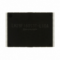
LH28F160S3T-L10A Sharp Microelectronics, LH28F160S3T-L10A Datasheet - Page 32

LH28F160S3T-L10A
Manufacturer Part Number
LH28F160S3T-L10A
Description
IC FLASH 16MBIT 100NS 56TSOP
Manufacturer
Sharp Microelectronics
Datasheet
1.LH28F160S3T-L10A.pdf
(56 pages)
Specifications of LH28F160S3T-L10A
Format - Memory
FLASH
Memory Type
FLASH
Memory Size
16M (2M x 8 or 1M x 16)
Speed
100ns
Interface
Parallel
Voltage - Supply
3 V ~ 3.6 V
Operating Temperature
0°C ~ 70°C
Package / Case
56-TSOP
Lead Free Status / RoHS Status
Contains lead / Request inventory verification
Other names
425-1838
LHF16KA6
LHF16KA6
Available stocks
Company
Part Number
Manufacturer
Quantity
Price
Part Number:
LH28F160S3T-L10A
Manufacturer:
SHARP
Quantity:
20 000
sharp
5 DESIGN CONSIDERATIONS
5.1 Three-Line Output Control
The device will often be used in large memory arrays.
SHARP
accommodate multiple memory connections. Three-
Line control provides for:
To use these control inputs efficiently, an address
decoder should enable CE# while OE# should be
connected to all memory devices and the system’s
READ# control line. This assures that only selected
memory
deselected memory devices are in standby mode.
RP#
POWERGOOD signal to prevent unintended writes
during system power transitions. POWERGOOD
should also toggle during system reset.
5.2 STS and Block Erase, Full Chip
STS is an open drain output that should be
connected to V
hardware method of detecting block erase, full chip
erase, (multi) word/byte write and block lock-bit
configuration
transitions low after block erase, full chip erase,
(multi) word/byte write or block lock-bit configuration
commands and returns to V
finished
alternate
Configuration command.
STS can be connected to an interrupt input of the
system CPU or controller. It is active at all times.
a. Lowest possible memory power dissipation.
b. Complete assurance that data bus contention will
not occur.
Erase, (Multi) Word/Byte Write and
Block Lock-Bit Configuration Polling
should
executing
devices
provides
STS
completion.
CC
be
by a pullup resistor to provide a
pin
have
connected
the
three
configurations,
internal
OH
active
In
control
when the WSM has
default
to
algorithm.
outputs
the
inputs
mode,
see
system
while
For
the
LHF16KA6
to
it
STS, in default mode, is also High Z when the device
is in block erase suspend (with (multi) word/byte write
inactive), (multi) word/byte write suspend or deep
power-down modes.
5.3 Power Supply Decoupling
Flash memory power switching characteristics require
careful device decoupling. System designers are
interested in three supply current issues; standby
current levels, active current levels and transient
peaks produced by falling and rising edges of CE#
and OE#. Transient current magnitudes depend on
the device outputs’ capacitive and inductive loading.
Two-line control and proper decoupling capacitor
selection will suppress transient voltage peaks. Each
device should have a 0.1µF ceramic capacitor
connected between its V
V
capacitors should be placed as close as possible to
package leads. Additionally, for every eight devices,
a 4.7µF electrolytic capacitor should be placed at the
array’s power supply connection between V
GND. The bulk capacitor will overcome voltage
slumps caused by PC board trace inductance.
5.4 V
Updating flash memories that reside in the target
system requires that the printed circuit board
designer pay attention to the V
The V
block erase, full chip erase, (multi) word/byte write
and block lock-bit configuration. Use similar trace
widths and layout considerations given to the V
power bus. Adequate V
decoupling will decrease V
overshoots.
PP
and GND. These high-frequency, low inductance
PP
PP
pin supplies the memory cell current for
Trace on Printed Circuit Boards
CC
and GND and between its
PP
PP
PP
supply traces and
voltage spikes and
Power supply trace.
Rev. 2.0
CC
and
30
CC


