LME49600TS/NOPB National Semiconductor, LME49600TS/NOPB Datasheet - Page 14
LME49600TS/NOPB
Manufacturer Part Number
LME49600TS/NOPB
Description
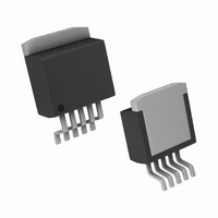
IC AMP BUFFER AUD HI FI TO-263-5
Manufacturer
National Semiconductor
Type
Class ABr
Datasheet
1.LME49600TSNOPB.pdf
(20 pages)
Specifications of LME49600TS/NOPB
Output Type
1-Channel (Mono)
Max Output Power X Channels @ Load
500mW x 1 @ 32 Ohm
Voltage - Supply
±2.25 V ~ 18 V
Features
Short-Circuit and Thermal Protection
Mounting Type
Surface Mount
Package / Case
D²Pak, TO-263 (5 leads + tab)
Amplifier Class
AB
No. Of Channels
1
Supply Voltage Range
± 2.25V To ± 18V
Load Impedance
32ohm
Operating Temperature Range
-40°C To +85°C
Amplifier Case Style
TO-263
No. Of Pins
5
Rohs Compliant
Yes
Number Of Channels
1
Voltage Gain Db
0.09 dB
Input Voltage Range (max)
36 V
Input Voltage Range (min)
4.5 V
Input Offset Voltage
60 mV at +/- 15 V
Supply Current
14.5 mA
Maximum Operating Temperature
+ 85 C
Mounting Style
SMD/SMT
Maximum Dual Supply Voltage
+/- 18 V
Minimum Operating Temperature
- 40 C
Lead Free Status / RoHS Status
Lead free / RoHS Compliant
Other names
*LME49600TS/NOPB
LME49600TS
LME49600TS


www.national.com
A copper plane may be placed directly beneath the tab. Ad-
ditionally, a matching plane can be placed on the opposite
side. If a plane is placed on the side opposite of the
LME49600, connect it to the plane to which the buffer’s metal
tab is soldered with a matrix of thermal vias per JEDEC Stan-
dard JESD51-5.
Determining Copper Area
Find the required copper heat sink area using the following
guidelines:
1. Determine the value of the circuit’s power dissipation, P
2. Specify a maximum operating ambient temperature, T
(MAX).
T
from junction to ambient, θ
fied such that T
temperature of 150°C.
3. Specify a maximum allowable junction temperature, T
(MAX)
is drawing maximum current (quiescent and load). It is pru-
dent to design for a maximum continuous junction tempera-
ture of 100°C to 130°C. Ensure, however, that the junction
temperature never exceeds the 150°C absolute maximum
rating for the part.
4. Calculate the value of junction to ambient thermal resis-
tance, θ
5. θ
in Figure 7. Choose a copper area that will guarantee the
specified T
of junction to ambient thermal resistance, θ
where:
T
T
LME49600’s environment
P
Note: The allowable thermal resistance is determined by the
maximum allowable temperature increase:
A
J(MAX)
A(MAX)
D(MAX)
by an amount that is dependent on the thermal resistance
JA
FIGURE 7. Thermal Resistance for 5 lead TO–263
, This is the LME49600’s die temperature when the buffer
(Note that the die temperature, T
as a function of copper area in square inches is shown
θ
= the maximum recommended junction temperature
JA
= the maximum recommended power dissipation
JA
= the maximum ambient temperature in the
= (T
J(MAX)
Package Mounted on 1oz. Copper
J(MAX)
J
does not exceed the absolute maximum die
for the calculated θ
- T
A(MAX)
JA
). Therefore, T
)/ P
D(MAX)
JA
. The maximum value
J
, will be higher than
(°C/W)
JA
A
, is defined as:
must be speci-
30029861
(1)
D
A
.
J
14
Thus, if ambient temperature extremes force T
the design maximum, the part must be de-rated by either de-
creasing P
using a larger copper area.
Procedure
1. First determine the maximum power dissipated by the
LME49600, P
a resistive load, and assuming equal supplies, P
en by:
where:
V
I
Equation (2) is for sinusoidal output voltages and (3) is for DC
output voltages
2. Determine the maximum allowable die temperature rise,
3. Using the calculated value of T
the required value of junction to ambient thermal resistance
combining equation 1 and equation 4 to derive equation 5:
4. Finally, choose the minimum value of copper area from
Figure 7 based on the value for θ
Example
Assume the following conditions: V
= 32Ω, I
C, T
Applying Equation (2):
Applying Equation (4):
Applying Equation (5):
S
S
=quiescent supply current (A)
= |V
P
A(MAX)
DMAX(AC)
P
EE
S
DMAX(DC)
| + V
= 15mA, sinusoidal output voltage, T
D
= 85°C.
to a safe level, reducing θ
T
P
D(MAX)
CC
= (I
= (15mA)(30V) + 900V
θ
RISE(MAX)
DMAX
JA
(V)
T
= (I
S
T
RISE(MAX)
= T
. For the simple case of the buffer driving
x V
RISE
= (I
S
θ
RISE(MAX)
x V
JA
S
S
) + (V
= T
= T
= 21.5°C/W
= 40°C/1.86W
S
x V
= 1.86W
) + (V
= 40°C
J(MAX)
J(MAX)
= 125°C – 85°C
S
S
) + (V
)
/ P
2
S
/ (2
)
- T
JA
- T
D(MAX)
2
RISE(MAX)
S
.
S
/ R
π
A(MAX)
A(MAX)
= |V
)
JA
2
2
2
L
R
/ 2
/ 142Ω
further or, if available,
(Watts)
L
EE
) (Watts)
π
(°C)
| + V
2
and P
R
L
RISE
J(MAX)
CC
D(MAX)
D(MAX)
= 30V, R
to exceed
= 125°
is giv-
, find
(2)
(3)
(4)
L
Related parts for LME49600TS/NOPB
Image
Part Number
Description
Manufacturer
Datasheet
Request
R

Part Number:
Description:
National Semiconductor [8-Bit D/A Converter]
Manufacturer:
National Semiconductor
Datasheet:
Part Number:
Description:
National Semiconductor [Media Coprocessor]
Manufacturer:
National Semiconductor
Datasheet:
Part Number:
Description:
Digitally Controlled Tone and Volume Circuit with Stereo Audio Power Amplifier, Microphone Preamp Stage and National 3D Sound
Manufacturer:
National Semiconductor
Datasheet:
Part Number:
Description:
Digitally Controlled Tone and Volume Circuit with Stereo Audio Power Amplifier, Microphone Preamp Stage and National 3D Sound
Manufacturer:
National Semiconductor
Datasheet:
Part Number:
Description:
AC97 Rev 2 Codec with Sample Rate Conversion and National 3D Sound
Manufacturer:
National Semiconductor
Part Number:
Description:
Manufacturer:
National Semiconductor
Datasheet:
Part Number:
Description:
Manufacturer:
National Semiconductor
Datasheet:
Part Number:
Description:
General Purpose, Low Voltage, Low Power, Rail-to-Rail Output Operational Amplifiers
Manufacturer:
National Semiconductor
Datasheet:
Part Number:
Description:
8-bit 20 MSPS flash A/D converter.
Manufacturer:
National Semiconductor
Datasheet:
Part Number:
Description:
Low Noise Quad Operational Amplifier
Manufacturer:
National Semiconductor
Datasheet:
Part Number:
Description:
Quad Differential Line Receivers
Manufacturer:
National Semiconductor
Datasheet:
Part Number:
Description:
Quad High Speed Trapezoidal? Bus Transceiver
Manufacturer:
National Semiconductor
Datasheet:
Part Number:
Description:
Dual Line Receiver
Manufacturer:
National Semiconductor
Datasheet:
Part Number:
Description:
TTL to 10k ECL Level Translator with Latch
Manufacturer:
National Semiconductor
Datasheet: